
HOME
Shop
  • English
  • 简体中文
HOME
Shop
  • English
  • 简体中文
  • Product Series

    • FPGA+ARM

      • GM-3568JHF

        • Introduction

          • GM-3568JHF Introduction
        • Quick Start

          • Preface
          • Environment Setup
          • Compilation Notes
          • Flashing Guide
          • Debugging Tools
          • Software Update
          • Viewing System Information
          • Test Commands
          • Application Compilation
          • Source Code Access
        • Peripherals & Interfaces

          • USB
          • Display and Touch
          • Ethernet
          • WIFI
          • Bluetooth
          • TF-Card
          • Audio
          • Serial Port
          • CAN
          • RTC
        • Application Development

          • UART Read/Write Demo
          • Key Detection Demo
          • LED Blink Demo
          • MIPI Screen Detection Demo
          • Read USB Device Information Demo
          • FAN Detection Demo
          • FPGA FSPI Communication Demo
          • FPGA DMA Read/Write Demo
          • GPS Debugging Demo
          • Ethernet Test Demo
          • RS485 Read/Write Demo
          • FPGA I2C Read/Write Demo
          • PN532 NFC Card-Reading Demo
          • TF Card Read/Write Demo
        • QT Development

          • ARM64 Cross-Compiler Environment Setup
          • Adding a QT Program to Boot Auto-Start
        • RKNN_NPU Development

          • RK3568 NPU Overview
          • Development Environment Setup
          • Run the Official YOLOv5 Example
        • FPGA Development

          • ARM and FPGA Communication
          • FPGA Development Manual
        • Others

          • Modifying the Root Filesystem
          • System Auto-Start Services
        • Downloads

          • Downloads
      • MB-E30P

        • Introduction

          • MB-E30P Introduction
        • Quick Start

          • Preface
          • Environment Setup
          • Compilation Instructions
          • Flashing Guide
          • Debugging Tools
          • Software Update
          • Viewing Information
          • Test Commands
          • Application Compilation
          • Source Code Acquisition
        • Peripherals & Interfaces

          • USB
          • Display and Touch
          • Ethernet
          • WIFI
          • Bluetooth
          • TF-Card
          • Audio
          • RTC
        • Application Development

          • Key Detection Demo
          • LED Blink Demo
          • MIPI Screen Detection Demo
          • Read USB Device Information Demo
          • FAN Detection Demo
          • FPGA FSPI Communication Demo
          • FPGA DMA Read/Write Demo
          • Ethernet Test Demo
          • FPGA IIC Read/Write Demo
          • PN532 NFC Card Reading Demo
          • TF Card Read/Write Demo
        • QT Development

          • ARM64 Cross-Compiler Environment Setup
          • Adding a QT Program to the Boot Auto-Start Service
        • RKNN_NPU Development

          • RK3568 NPU Overview
          • Development Environment Setup
          • Run the Official YOLOv5 Example
          • Model Conversion In Detail
          • Run Custom Models on the Board
        • FPGA Development

          • ARM and FPGA Communication
          • FPGA Development Manual
        • Others

          • Modifying the Root Filesystem
          • System Auto-Start Service
        • Downloads

          • Downloads
    • ShimetaPi

      • M4-R1

        • Introduction

          • M4-R1 Introduction
        • Quick Start

          • OpenHarmony Overview
          • Image Burning
          • Application Development Quick Start
          • Device Development Quick Start
        • Application Development

          • ArkUI

            • ArkTS Language Overview
            • UI Components - Row Container Introduction
            • UI Components - Column Container Introduction
            • UI Components - Text Component
            • UI Components - Toggle Component
            • UI Components - Slider Component
            • UI Components - Animation Component & Transition Component
          • Documentation

            • OpenHarmony Official Materials
          • Development Notes

            • Full-SDK Replacement Tutorial
            • Introducing and Using Third-Party Libraries
            • HDC Debugging
            • Restore Factory Mode via Command Line
            • Upgrade App to System Permission
          • First App

            • Build Your First ArkTS Application - HelloWorld
          • Demos

            • Serial-Debug-Assistant Application Demo
            • Writing-Board Application Demo
            • Digital Clock Application Demo
            • Wi-Fi Information Acquisition Application Demo
        • Device Development

          • Ubuntu Development

            • Environment Setup
            • Download Source Code
            • Compile Source Code
          • DevEco Device Tool

            • Tool Introduction
            • Development Environment Construction
            • Import the SDK
            • HUAWEI DevEco Tool Function Introduction
        • Kernel Peripherals & Interfaces

          • Guide
          • Device Tree Introduction
          • NAPI Introduction
          • ArkTS Introduction
          • NAPI Development Hands-on Demo
          • GPIO Introduction
          • I2C Communication
          • SPI Communication
          • PWM Control
          • UART Communication
          • TF Card (MicroSD)
          • Screen (Display)
          • Touch
          • Ethernet
          • M.2 SSD
          • Audio
          • WIFI & BT
          • Camera
        • Downloads

          • Downloads
      • M5-R1

        • Introduction

          • M5-R1 Development Docs
        • Quick Start

          • Image Burning
          • Environment Setup
          • Download Source Code
        • Peripherals & Interfaces

          • Raspberry Pi Interfaces
          • GPIO Interface
          • I2C Interface
          • SPI Communication
          • PWM Control
          • Serial Port Communication
          • TF Card
          • Display
          • Touch
          • Audio
          • RTC
          • Ethernet
          • M.2
          • MINI-PCIE
          • Camera
          • WIFI & BT
        • Downloads

          • Downloads
      • Pico-G1

        • Product Overview

          • Product Introduction
          • SDK Version Information
        • Quick Start

          • Development Environment Setup
          • Image Build
          • Image Flashing
          • System Login
          • Network Configuration
          • File Transfer
          • SDK Directory Structure
          • Deploying Your First Application
          • Deploying Your First Driver
          • Mounting an SD Card
        • Peripherals & Interfaces

          • GPIO Control
          • UART Serial Communication
          • I2C Communication
          • SPI Communication
        • MPP Media Development

          • MPP Media Processing Software
          • Image Processing Chain
          • Video Input
          • Image Encoding
        • NPU & AI

          • NPU Driver and Runtime Library Architecture
          • .xmm Model Loading
          • SVP Video Processing
          • AI Noise Reduction (AI_NR)
        • Application Samples

          • Encryption/Decryption Application
          • ADC Acquisition Application
          • Low-Power Application
          • Audio Processing Application
          • Video Encoding Application
          • Video Input Application
          • Video Graphics Subsystem (VGS) Application
          • 08 Region Overlay Application
          • 09 Intelligent Video Engine Application
          • 10 UVC Webcam Application
          • 11 All-in-One Quickstart Application
          • 12 FPN Correction Application
          • 13 Regional Motion Detection Application
          • 14 MTCNN Face Detection Application
        • Expansion Board Peripheral Examples

          • 00 - Pico Expansion Board Peripheral Examples Overview
          • 01 - OLED Display Application
          • 02 - TFT Display Application
          • 03 - MPU6050 Gyroscope Application
          • 04 - ADC Acquisition Application
          • 05 - Passive Buzzer Application
          • 06 - MQ Gas Sensor Application
          • 07 - GPS Positioning Application
          • 08 - SHT20 Temperature & Humidity Application
          • 09 - Ultrasonic Ranging Application
          • 10 - SpO2 Sensor Application
          • 11 - DC Motor Control Application
          • 12 - Servo Control Application
    • OpenHarmony

      • SC-3568HA

        • Introduction

          • SC-3568HA Overview
        • Quick Start Guide

          • OpenHarmony Overview
          • Image Flashing
          • Setting Up the Development Environment
          • Hello World Application and Deployment
        • Application Development

          • ArkUI

            • Introduction to ArkTS Language
            • Introduction to UI Components and Practical Applications (Part 1)
            • Introduction to UI Components and Practical Applications (Part 2)
            • Introduction to UI Components and Practical Applications (Part 3)
          • Expand

            • Getting Started Guide
            • Referencing and Using Third-Party Libraries
            • Application Compilation and Deployment
            • Command-Line Factory Reset
            • System Debugging -- HDC Debugging
            • APP Stability Testing
            • Chapter 7 Application Testing
        • Device Development

          • Environment Setup
          • Download Source Code
          • Compiling Source Code
        • Peripheral And Interface

          • Raspberry Pi interface
          • GPIO Interface
          • I2C Interface
          • SPI communication
          • PWM (Pulse Width Modulation) control
          • Serial port communication
          • TF Card
          • Display Screen
          • Touch
          • Audio
          • RTC
          • Ethernet
          • M.2
          • MINI-PCIE
          • Camera
          • WIFI&BT
          • Raspberry Pi expansion board
        • Downloads

          • Downloads
      • M-K1HSE

        • Introduction

          • M-K1HSE Introduction
        • Quick Start

          • Development environment construction
          • Source code acquisition
          • Compilation Notes
          • Burning Guide
        • Application Development

          • Application Development Environment Setup
          • First Application - Hello World
        • Peripherals and interfaces

          • 01 Audio
          • 02 RS485
          • 03 Display
        • System customization development

          • System transplant
          • System customization
          • Driver Development
          • System Debugging
          • OTA Update
        • Downloads

          • Downloads
    • HVS Camera

      • Quick Start

        • SDK Overview
        • Downloads
        • Your First C++ Program
        • Python Data Analysis
        • MultiVision Studio
      • Development

        • Programming Guides

          • Open Camera
          • Read Events
          • Recording & Replay
          • Event Processing (Denoising)
          • Display & Visualization
          • Tuning
          • Capture APS Image
        • Toolkit SDK

          • Hybrid Vision Toolkit
          • Quick Start
          • C++ API
          • Python API
        • Algorithm

          • Hybrid Vision Algo
          • Hybrid Vision Algo API
          • Windows Algo SDK
        • Samples Overview
        • Applications
      • Fundamentals

        • Event Camera Fundamentals
        • HVS Hybrid Vision
        • Event Visualization
        • Data Formats Reference
        • Glossary
        • Bias & Tuning
        • Video Tutorials
      • USB Cameras

        • HVS Camera Quick Start
        • Networking Capabilities

          • HVS Camera System Architecture
          • EVS Network Server
          • EVS Time Sync
          • Web Window
        • HVS Camera Compatibility Matrix
        • FAQ & Troubleshooting Guide
        • Products

          • CF-NRS1 (Lingguang No.1 Hybrid Vision Camera)
      • MIPI Modules

        • MIPI Module Quick Start
        • Carrier Boards

          • RDK X5 Carrier Board Adaptation
          • Raspberry Pi Carrier Board Adaptation
          • Digua Pi Carrier Board Adaptation
          • ShimeTai Board Carrier Board Adaptation
        • MIPI Module Compatibility Matrix
        • Products

          • EVS_003 Sensor Module
    • AI-model

      • 1684XB-32T

        • Introduction

          • AIBOX-1684XB-32 Introduction
        • Quick Start

          • First Use
          • Network Configuration
          • Disk Usage
          • Memory Allocation
          • Fan Control Strategy
          • Firmware Upgrade
          • Cross Compilation
          • Model Quantization
        • Application Development

          • Development Overview

            • Sophgo SDK Development
            • Sophgo Demo Introduction
          • Large Language Models

            • Deploying Llama3 Example
            • Sophon LLM_api_server Development
            • Deploying MiniCPM-V-2_6
            • Qwen-2-5-VL Image and Video Recognition Demo
            • Qwen3-chat Demo
            • Qwen3-Qwen Agent-MCP Development
            • Qwen3-langchain-AI Agent
          • Deep Learning

            • ResNet (Image Classification)
            • LPRNet (License Plate Recognition)
            • SAM (General Image Segmentation Foundation Model)
            • YOLOv5 (Object Detection)
            • OpenPose (Human Keypoint Detection)
            • PP-OCR (Optical Character Recognition)
        • Downloads

          • Downloads
      • 1684X-416T

        • Introduction

          • AIBOX-1684X-416 Introduction
        • Demo Quick Guide

          • ShimeTai Intelligent Monitoring Demo Quick Usage Guide
      • RDK-X5

        • Introduction

          • RDK-X5 Hardware Introduction
        • Quick Start

          • RDK-X5 Quick Start
        • Application Development

          • AI Online Model Development

            • Experiment 01 - Access Volcengine Doubao AI
            • Experiment 02 - Image Analysis
            • Experiment 03 - Multimodal Visual Analysis & Localization
            • Experiment 04 - Multimodal Image-Text Comparison
            • Experiment 05 - Multimodal Document/Table Analysis
            • Experiment 06 - Camera-based AI Visual Analysis
          • Large Language Models

            • Experiment 01 - Speech Recognition
            • Experiment 02 - Voice Conversation
            • Experiment 03 - Multimodal Image Analysis - Voice
            • Experiment 04 - Multimodal Image Comparison - Voice
            • Experiment 05 - Multimodal Document Analysis - Voice
            • Experiment 06 - Multimodal Vision Application - Voice
          • ROS2 Basics

            • Experiment 01 - Environment Setup
            • Experiment 02 - Create & Build a Workspace Package
            • Experiment 03 - Run ROS2 Topic Communication Node
            • Experiment 04 - ROS2 Camera Application
          • 40-pin IO Development

            • Experiment 01 - GPIO Output (LED Blink)
            • Experiment 02 - GPIO Input
            • Experiment 03 - Button-controlled LED
            • Experiment 04 - PWM Output
            • Experiment 05 - Serial Output
            • Experiment 06 - I2C Experiment
            • Experiment 07 - SPI Experiment
          • USB Module Usage

            • Experiment 01 - USB Voice Module Usage
            • Experiment 02 - Sound Source Localization Module
          • Machine Vision Practice

            • Experiment 01 - Open USB Camera
            • Experiment 02 - Color Recognition
            • Experiment 03 - Gesture Recognition
            • Experiment 04 - YOLOv5 Object Detection
      • RDK-S100

        • Introduction

          • RDK-S100 Hardware Introduction
        • Quick Start

          • RDK-S100 Quick Start
        • Application Development

          • AI Online Model Development

            • Experiment 01 - Access Volcengine Doubao AI
            • Experiment 02 - Image Analysis
            • Experiment 03 - Multimodal Visual Analysis & Localization
            • Experiment 04 - Multimodal Image-Text Comparison
            • Experiment 05 - Multimodal Document/Table Analysis
            • Experiment 06 - Camera-based AI Visual Analysis
          • Large Language Models

            • Experiment 01 - Speech Recognition
            • Experiment 02 - Voice Conversation
            • Experiment 03 - Multimodal Image Analysis - Voice
            • Experiment 04 - Multimodal Image Comparison - Voice
            • Experiment 05 - Multimodal Document Analysis - Voice
            • Experiment 06 - Multimodal Vision Application - Voice
          • ROS2 Basics

            • Experiment 01 - Environment Setup
            • Experiment 02 - Create & Build a Workspace Package
            • Experiment 03 - Run ROS2 Topic Communication Node
            • Experiment 04 - ROS2 Camera Application
          • 40-pin IO Development

            • Experiment 01 - GPIO Output (LED Blink)
            • Experiment 02 - GPIO Input
            • Experiment 03 - Button-controlled LED
            • Experiment 04 - PWM Output
            • Experiment 05 - Serial Output
            • Experiment 06 - I2C Experiment
            • Experiment 07 - SPI Experiment
          • USB Module Usage

            • Experiment 01 - USB Voice Module Usage
            • Experiment 02 - Sound Source Localization Module
          • Machine Vision Practice

            • Experiment 01 - Open USB Camera
            • Experiment 02 - Image Processing Basics
            • Experiment 03 - Object Detection
            • Experiment 04 - Image Segmentation
      • RK1828

        • Introduction

          • M5-182X-A1 AI Edge Box - Product Introduction
          • M5-182X-A1 Hardware Specifications
          • M5-182X-A1 Usage & Safety
        • Quick Start

          • M5-182X-A1 Image Flashing
          • RK182X Hardware Installation & Verification
          • RK182X Development Environment Quick Setup
          • RK182X SDK Overview
          • RK182X Environment Setup in Detail
          • RK182X Quick Start
          • Vendor SDK Data Extraction Record
        • Development Guide

          • ClawChips Architecture and Principles
          • SKILL User Manual
          • RK182X Series LLM Inference (RK1828 Model)
          • RK182X Series CNN Inference (RK1828 Model)
          • Model Conversion
          • RK182X AI Agent Application Development Guide
          • RK182X Industrial Anomaly Detection Application
        • SDK Reference

          • RKNN3-SDK Overview

            • RKNN3 SDK Overview
          • RKNN3-Toolkit

            • RKNN3 Toolkit Installation and Usage
          • RKLLM

            • RKLLM On-Device LLM Inference
          • RK182X Series NPU Overview and Architecture (RK1828 Model)
          • RK182X INT8 Quantized Inference Deployment
          • RK182X MPP Multimedia Framework
          • MPP Details

            • RK182X Video Decoding
            • RK182X Video Encoding
          • NPU Details

            • RKNN Model Conversion
            • RK182X NPU INT8 Quantized Inference
            • RK182X Multi-Model Parallel Inference
          • RGA Details

            • RK182X RGA 2D Graphics Acceleration
          • VPU Details

            • RK182X VPU Codec
        • Hardware Reference

          • RK182X Series Hardware Architecture Overview (RK1828 Model)
          • RK182X Pin Definitions and Multiplexing Configuration
          • RK182X Pin Definitions
          • RK182X Power Management
          • RK182X Clock and PLL Configuration
          • RK182X Clock and Frequency Configuration
        • Tutorials

          • Hello World
          • Hello RK1828 - The First Program
          • RTSP Streaming
          • RTSP Streaming + AI Analysis
          • ShiMetaPi AI Lobster One-Click Deployment
          • PaddleOCR-VL Text Recognition
          • Qwen3-1.7B LLM Text Chat
          • AI Multi-View Inspection (Qwen3-VL Wrapper)
          • YOLOv5 Object Detection
        • Downloads

          • Downloads
        • FAQ

          • FAQ
    • Core-Board

      • C-3568BQ

        • Introduction

          • C-3568BQ Overview
      • C-3588LQ

        • Introduction

          • C-3588LQ Overview
      • GC-3568JBAF

        • Introduction

          • GC-3568JBAF Overview
      • C-K1BA

        • Introduction

          • C-K1BA Overview
    • Software Platform

      • ShiMetaPi Workbench

        • Introduction

          • Product Overview
          • Core Architecture
          • Feature Entries
          • Supported Hardware
          • Release Notes
        • Quick Start

          • Install & Login
          • Connect the Device
          • Set Up the Environment
          • Connect to AIHub
          • First Inference
        • User Guide

          • Workspace Overview
          • Device Manager
          • Model Market
          • One-Click Deploy
          • Vision — SVP
          • Vision - Custom Models
          • shimeta-py IDE
          • Terminal
          • Agent Debug Assistant
          • Settings and Resources
        • FAQ

          • Installation & Login
          • Device Connection
          • Models & Deployment
          • Vision & Runtime
          • Settings & Other
      • ShimetaPi Repository

        • Introduction

          • ShimetaPi Software Repository
        • Pico G1 (GK7206)

          • Quick Start

            • Installation & First Inference
            • shimeta_infer — Image Inference
            • shimeta_camera — Real-time Camera Inference
            • SVP Scene Detection
            • File Transfer & Built-in Model Reference
            • FAQ
          • HTTP API & Python SDK

            • HTTP API Reference
      • Model Fine-tuning Platform

        • Introduction

          • Model Training Platform
        • Quick Start

          • Register & Login
          • Create Your First Model (30-Minute Quick Experience)
        • Training Guide

          • Data Preparation & Annotation
          • Training Parameter Configuration
          • Start & Monitor Training
          • Model Evaluation & Testing
        • Model Deployment

          • Export Model
          • Deploy to Edge Device

MPP Media Processing Software

1 Overview

The Media Processing Platform (MPP) supports rapid development of application software. This platform hides chip-specific low-level processing from the application software and provides the MPI (MPP Program Interface) directly to the application to complete the corresponding functions. The platform enables rapid development of: input video capture, H.265/JPEG encoding, H.265 decoding, video output display, video image preprocessing (including denoising, enhancement, sharpening), image geometric correction, image stitching, black-and-white image fusion, image stabilization, audio capture and output, audio encoding/decoding, and more.

1.1 MPP Architecture

The MPP architecture is divided, from bottom to top, into the hardware layer, the operating system layer, the OS adaptation layer, the media processing platform, other drivers, and the application layer, as shown below.
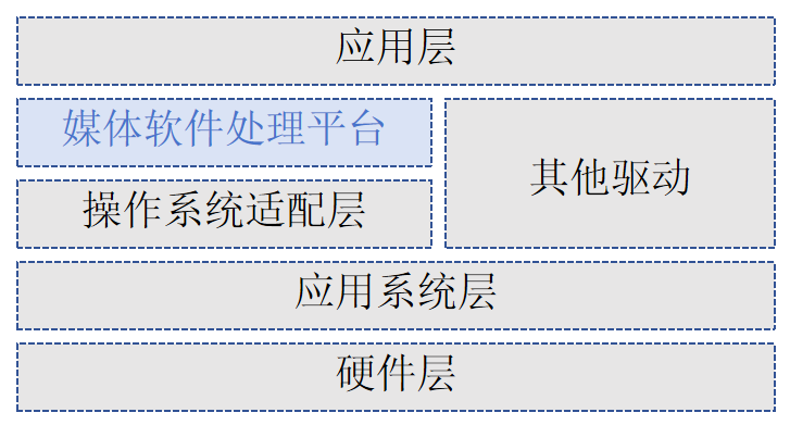
MPP typical system layer diagram

  • Hardware layer: consists of the chip and necessary peripheral components, including Flash, DDR, video Sensor or AD, audio AD, etc.
  • Operating system layer: an OS based on Linux.
  • OS adaptation layer: provides the underlying system-call functions, abstracts OS differences, and supports running the media processing platform on different operating systems or versions.
  • Media Processing Platform (MPP): built on the OS adaptation layer, it controls the chip to complete the corresponding media processing functions. It hides hardware processing details from the application layer and provides an API to the application layer.
  • Other drivers: drivers for hardware processing units outside the media processing platform, such as CIPHER and RTC drivers.
  • Application layer: application software systems developed by the user, built on the media processing platform and other drivers.

1.2 MPP Video Stream

Note

In this document, "VI online/offline" refers to the online/offline mode between VI_CAP and VI_PROC. In this document, "VPSS online/offline" refers to the online/offline mode between VI_PROC and VPSS. In this document, "GDC online/offline" refers to the online/offline mode between GDC and VPSS. VI_PROC and GDC are always in offline mode.

The MPP video stream is shown below:
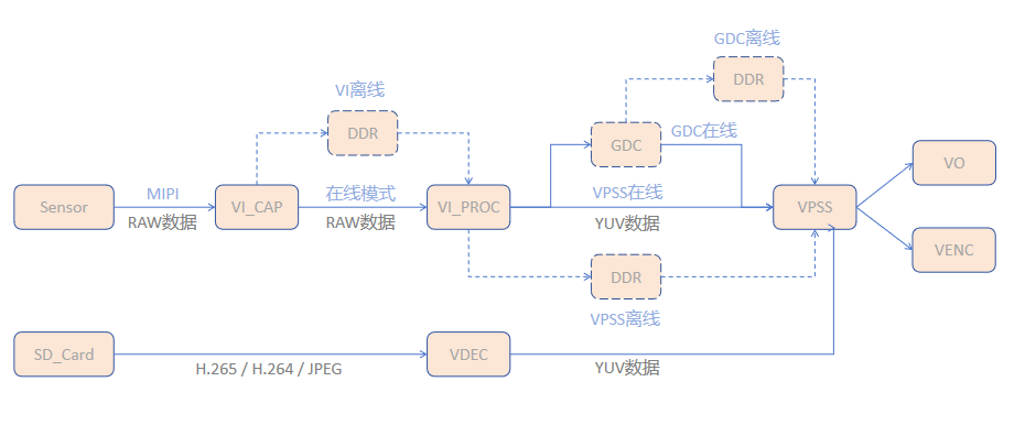
MPP video stream

  • VI_CAP module: obtains raw image data from the sensor via the MIPI protocol.
  • VI_PROC module: crops, denoises, and otherwise processes the raw image data, and outputs multiple image streams at different resolutions.
  • GDC module: performs geometric transforms on the image, such as fisheye correction, lens distortion correction, rotation, and perspective transform (optional).
  • VPSS module: receives images sent from VI, GDC, and VDEC, can perform image enhancement, sharpening, stitching, and other processing, and can output multiple image streams of different resolutions from the same source.
  • Encoding module: receives the image data output by VPSS, encodes it according to different protocols, and outputs the corresponding bitstream.
  • VO module: receives the images output by VPSS, performs playback control and other processing, and outputs them to peripheral video devices according to the user-configured output protocol.

pipe mode configuration notes

  1. For any pipe, GDC and VPSS cannot both be in online mode at the same time.
  2. Only pipe0 supports VI online mode.
  3. When pipe0 is in VI offline mode, the GDC mode and VPSS mode of all other pipes must match those of pipe0.

2 System Control Module

Based on chip characteristics, system control performs the basic system initialization, and also manages abnormal exits of each MPP (Media Processing Platform) service module, provides version information for the current MPP system, provides binding functions, provides large-block physical memory management, and provides OST and QOS value configuration for modules.

2.1 SYS Module Initialization and De-initialization

SYS module initialization specifies the working mode between modules in a pipe. Any MPP service must perform system initialization before running; after the service ends, you must perform system de-initialization to release resources. Example (required header: xmedia_sys.h):

xmedia_s32 mpp_sys_init()
{
    xmedia_s32 ret = XMEDIA_SUCCESS;
    ret=xmedia_sys_exit();
    if(ret!=XMEDIA_SUCCESS)
    {
        printf("xmedia_sys_exit failed !\n");
        return ret;
    }
    xmedia_sys_config sys_config={0};
    /*
     |Note:
     |  1. For any pipe, GDC and VPSS cannot both be in online mode at the same time.
     |  2. Only pipe0 supports VI online mode.
     |  3. When pipe0 is in VI offline mode, the GDC mode and VPSS mode of all other pipes must match those of pipe0.
     */
    sys_config.pipe_mode[0].vicap_viproc_mode = XMEDIA_WORK_MODE_ONLINE;
    sys_config.pipe_mode[0].viproc_vpss_mode = XMEDIA_WORK_MODE_ONLINE;
    sys_config.pipe_mode[0].gdc_vpss_mode =XMEDIA_WORK_MODE_OFFLINE;
    ret=xmedia_sys_init(&sys_config);
    if(ret!=XMEDIA_SUCCESS)
    {
        printf("xmedia_sys_init failed !\n");
        return ret;
    }
    else
    {
        printf("xmedia_sys_init success !\n");
        return XMEDIA_SUCCESS;
    }

}

Usage notes

  1. In a single process, repeated initialization still returns success, but it has no actual effect on the running state of MPP; the first valid configuration is the effective result. To change the initialization configuration, call xmedia_sys_exit first.

  2. In multi-process, each process must perform initialization. Only one valid configuration (non-null input parameter) is supported. If process a has been initialized with a non-null input parameter, the input parameter of other processes' initialization must be the same as that of process a or null; if process a has been initialized with a null input parameter, it has no effect on other processes' initialization.

  3. The pipe numbers of VI and VPSS on the same data path must be identical.

2.2 Video Buffer (VB) Management

The video buffer pool mainly provides large-block physical memory management for media services. It is responsible for memory allocation and reclamation, makes full use of the buffer pool, and allows physical memory resources to be used reasonably across media processing modules. A video buffer pool consists of a set of buffer blocks of the same size with contiguous physical addresses. A common video buffer pool must be configured before any MPP service. Depending on the service, the number of common buffer pools, the block size, and the number of blocks differ.

  • Common buffer pool configuration:

    The system supports configuring multiple common buffer pools, each containing several blocks of the same size. During configuration, use the commont_pool member of the xmedia_vb_cfg structure to specify the number of pools and the block size and count of each pool.

    • Block size: must be calculated based on the size and pixel format of the largest-resolution image in the service; can be obtained through xmedia_vb_get_buffer_config.
    • Block count: must be evaluated based on the number of concurrent service streams; too few causes block acquisition failures, while too many wastes memory.
  • Module-private buffer pool: In addition to common buffer pools, some modules (such as ISP and VDEC) also support configuring module-private buffer pools for optimization of specific service scenarios. This is configured through the supplement_config member of the xmedia_vb_cfg structure.

  • Buffer block acquisition and release:

    • Acquire: xmedia_mpi_vb_get_block, gets a free block from the specified common buffer pool.
    • Release: xmedia_mpi_vb_release_block, a block must be released after use, otherwise the buffer pool will be exhausted.

Note

Because other modules depend on the common buffer pool, vb initialization must be performed before other modules are initialized (called after sys initialization). It can be called multiple times and returns success, but only the first configuration takes effect.


xmedia_s32 mpp_vb_init()
{
    xmedia_s32 ret = XMEDIA_SUCCESS;

    ret = xmedia_vb_exit();
    if(ret!=XMEDIA_SUCCESS)
    {
        printf("xmedia_vb_exit failed !\n");
        return ret;
    }

    xmedia_vb_config vb_config={0};// The configuration must be zeroed first; otherwise random non-zero values may appear, causing an illegal configuration and vb pool initialization failure.
    /*
    #define XMEDIA_VB_SUPPLEMENT_ISP_INFO_ENABLE     1
    #define XMEDIA_VB_SUPPLEMENT_VDEC_INFO_ENABLE    (1 << 1)
    supplement_config: supplemental memory pool configuration; bit[0] and bit[1] are valid, the rest are illegal.
    bit[0]: 1 enables ISP memory allocation, 0 disables it;
    bit[1]: 1 enables VDEC memory allocation, 0 disables it.
    */
    vb_config.supplement_config=XMEDIA_VB_SUPPLEMENT_ISP_INFO_ENABLE|XMEDIA_VB_SUPPLEMENT_VDEC_INFO_ENABLE;
    vb_config.max_pool_cnt = 25;//Maximum number of memory pools


    xmedia_vb_base_info vb_base_info = {0};
    vb_base_info.video_fmt = XMEDIA_VIDEO_FMT_LINEAR;//Video storage format
    vb_base_info.pixel_fmt = XMEDIA_VIDEO_PIXEL_FMT_YVU_SEMIPLANAR_422;//Pixel format
    vb_base_info.cmp_mode = XMEDIA_VIDEO_COMPRESS_MODE_NONE;//Image compression mode
    vb_base_info.bit_width = XMEDIA_VIDEO_DATA_WIDTH_8;//Data width
    vb_base_info.width = 1920;//Width
    vb_base_info.height = 1080;//Height
    vb_base_info.align = DEFAULT_ALIGN;//Alignment
    vb_base_info.ainr_attr.ainr_en = XMEDIA_FALSE;//AINR disabled

    xmedia_vb_cal_cfg vb_cal_cfg = {0};
    xmedia_vb_get_buffer_config(&vb_base_info,&vb_cal_cfg);//Calculate the block size

    vb_config.common_pool[0].block_size = vb_cal_cfg.vb_size;//Block size - total size of a video image frame
    vb_config.common_pool[0].block_cnt = 3;//Number of blocks
    vb_config.common_pool[0].map_mode = XMEDIA_VB_MAP_MODE_NONE;//Kernel virtual address mapping mode of the VB
    /* When mmz_name is all zero, the pool is created from the anonymous mmz zone by default */

    ret = xmedia_vb_init(&vb_config);

    if(ret!=XMEDIA_SUCCESS)
    {
        printf("xmedia_vb_init failed, ret = 0x%x !\n", ret);
        return ret;
    }
    else
    {
        printf("xmedia_vb_init success !\n");
        return XMEDIA_SUCCESS;
    }
}

2.3 Binding Mechanism

MPP supports a module binding mechanism. Through the binding API xmedia_sys_bind, a data receiver binds a data source to establish the relationship between the two (only a data receiver is allowed to bind a data source). After binding, data generated by the data source is automatically sent to the receiver, eliminating the need for frequent application-layer intervention. The binding relationships supported by MPP are shown in the table below:

Data sourceData receiver
VIVPSS / MCF
MCFVPSS
VPSSVO / VENC
VDECVPSS / VO

Required Headers and Libraries

Headers: common.h, xmedia_sys.h

Library: libxmedia_common.a

  • Binding API:
//Establish a binding:
xmedia_s32 xmedia_sys_bind(const xmedia_chn_info *src_chn,const xmedia_chn_info *dest_chn);
//Unbind:
xmedia_s32 xmedia_sys_unbind(const xmedia_chn_info *src_chn,const xmedia_chn_info *dest_chn);

Note

  1. A single data receiver can only be bound to one data source.

  2. VI and VDEC, as data sources, send data to other modules by channel; the user should set the device number to 0, and the SDK does not check the input device number. In all other cases, both the device number and channel number must be specified.

Edit this page on GitHub
Next
Image Processing Chain