
Image Flashing
This document mainly describes the flashing features of the FastBurn tool.
FastBurn Tool Installation
Step 1: Copy the FastBurn tool package from the SDK release package directory (path: $SDK_DIR\tools\windows\burning-tool\FastBurn-x.x.xx.zip) to a local drive on your PC and extract it. 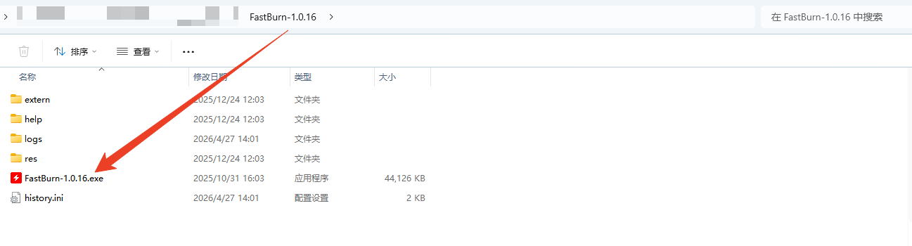 Step 2: Double-click
 FastBurn-x.x.xx.exe in the tool directory to open FastBurn. 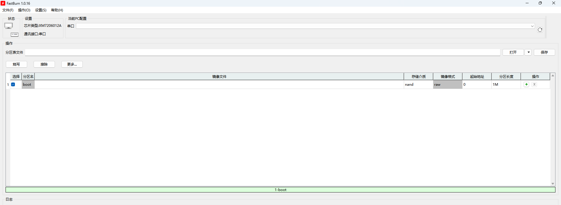
1. Flashing via Serial Port
Note
Install the serial driver required by your USB-to-TTL module yourself.
The FT232 driver is included in the SDK release package at:
sdk/tools/windows/burning-tools/ftdi-driver/FTDI-CDM-Driver.exeDouble-click the installer and follow the wizard to complete installation.
Step 1: On the tool interface, first select the chip type, then select the communication interface (such as "Serial Port"), and choose the corresponding port number. 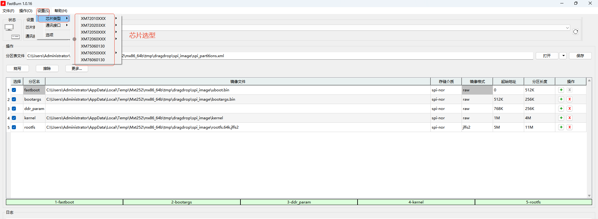

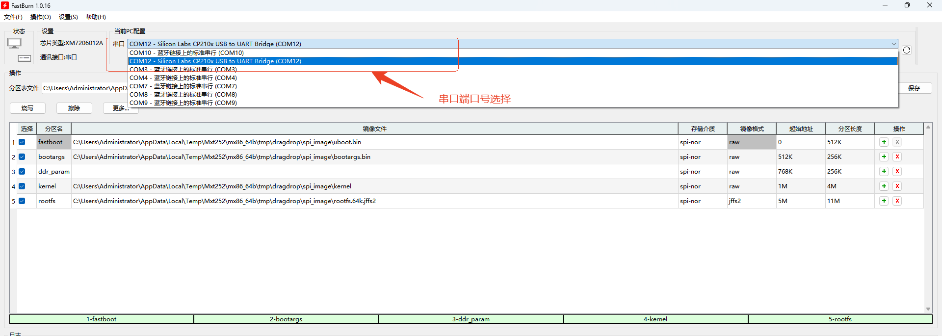
Step 2: Add the image files (directory path shown below) to FastBurn. After loading, FastBurn automatically recognizes the partition table information in the images. To configure the partition table manually, see 4. Configure Partition Table Information.
~/GK7206$ ls out/xm7206v12a/image/
emmc_image  nand_image  spi_image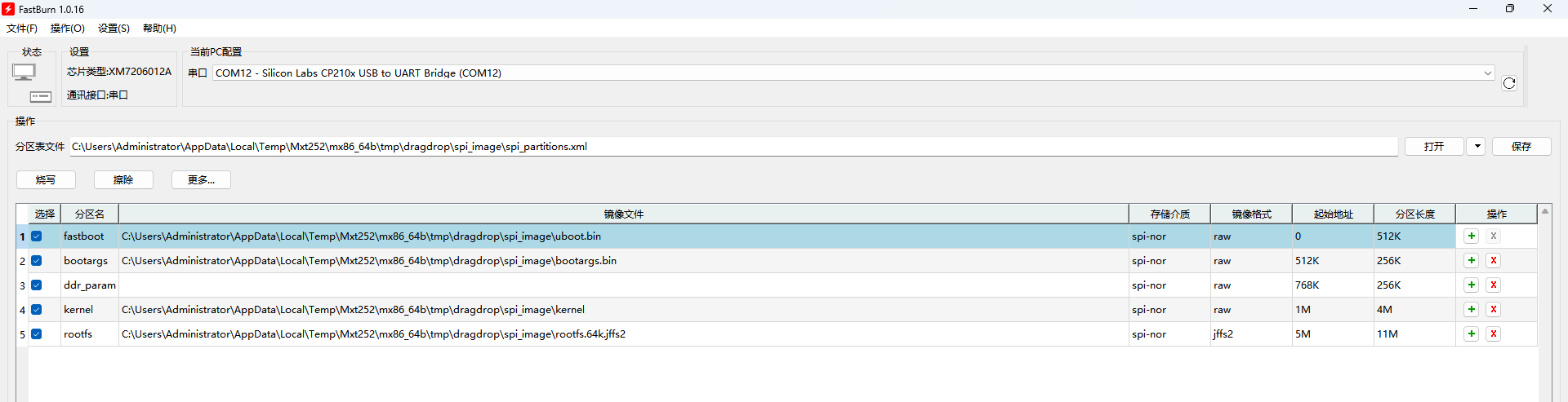
Step 3: Connect the board according to the selected communication interface, click the Write button, and press the RESET button on the board to start flashing.
2. Flashing via Serial + USB
2.1 USB Driver Installation
To flash with Serial + USB, you must first install the USB driver. The installation steps are as follows:
Method 1:
Step 1: Put Pico-G1 into USB device mode
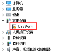
Press and hold the boot button while powering on the Pico-G1 to put the device into USB device mode. At this point, in Device Manager on the PC, the USB device will appear with a yellow exclamation mark as shown below.
Step 2: Install the driver following the FastBurn prompts. 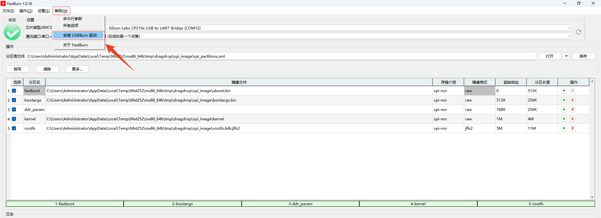
Step 3: After installation completes, the yellow exclamation mark disappears. Press the reset button to reboot the Pico-G1. 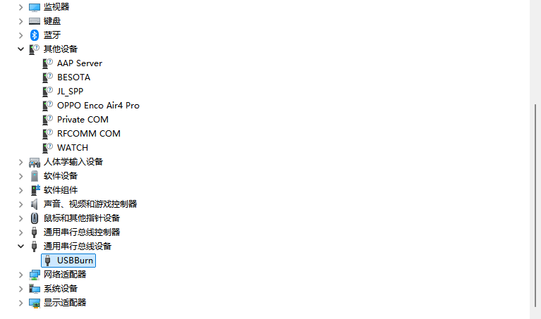
Method 2:
Step 1: Put Pico-G1 into USB device mode
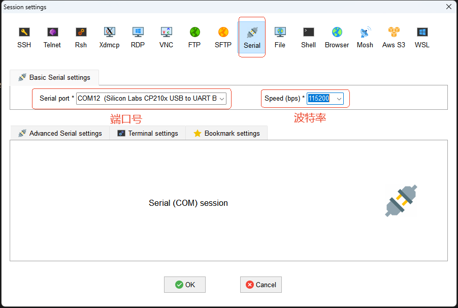
Connect the PC to the Pico-G1 with a USB cable, and connect to the Pico-G1 via a serial port in Mobaxterm. 
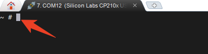
 Press Enter; the following prompt indicates a successful connection.
Press the RESET button on the Pico-G1 board, and keep pressing Enter in the Mobaxterm serial terminal on the PC to interrupt the auto-boot flow and enter the U-Boot command-line interface. 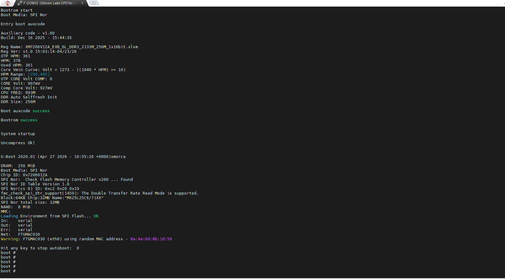
Run the usb device command in the U-Boot command-line interface, then check Device Manager on the PC. At this point, the PC will detect the USB device with a yellow exclamation mark as shown below.
Step 2: Install the driver following the FastBurn prompts.
Step 3: After installation completes, the yellow exclamation mark disappears. Press the reset button to reboot the Pico-G1.
2.2 Flashing Steps
Same as Serial; just change the communication method to Serial + USB.
3 Flashing via USB
Note
The flashing method is the same as USB + Serial, but the handshake steps differ. The handshake is: Press and hold the Boot button, click the Reset button, then release the Reset button.
4 Configure Partition Table Information
The partition table describes how the Flash storage space is divided, including each partition's name, start address, size, and the image file to flash. When FastBurn writes firmware, it uses the partition table to write each image to the specified location in Flash. Common partitions include fastboot, bootargs, ddr_param, kernel, rootfs, etc. The partition table may differ across platforms, Flash capacities, and system solutions.
Generally, if you use the partition table provided by default in the SDK and the firmware image size has not changed, you do not need to modify the partition table. However, you need to check and reconfigure the partition table in the following scenarios:
- Image file size exceeds the original partition size
When an image grows beyond its reserved partition space, the corresponding partition must be enlarged. For example: the kernel image exceeds the kernel partition size; the rootfs image exceeds the rootfs partition size; flashing reports errors such as image size too large or partition size not enough.
Solution: Re-plan the partition sizes based on the actual image sizes.
2. Flash capacity change
If the Flash capacity used by the hardware changes, for example: switching from 16 MB SPI NOR Flash to 32 MB, from 256 MB NAND Flash to 128 MB, or the eMMC capacity changes;
Solution: Re-adjust the partition layout for the new storage capacity to avoid partitions exceeding the Flash range or failing to fully use the new space.
3. Adding, removing, or adjusting partitions
When system features change, you may need to add or adjust partitions. For example: adding a recovery partition, a userdata partition, app, config, or factory partitions; removing unused partitions; merging multiple small partitions; resizing the rootfs or user data partitions; and so on.
Solution: You need to update the partition table accordingly and ensure the partition information in boot parameters or the device tree stays consistent with it.
4. OTA upgrade scheme change
If the system needs to support OTA upgrades, especially an A/B partition upgrade scheme, the partitions usually need to be re-planned. For example:
kernel_a, kernel_b, rootfs_a, rootfs_b, recovery, ota, userdata
OTA schemes usually have specific requirements on partition size and order, so the partition table must be reconfigured to match the upgrade scheme.
5. Boot method or system scheme change
If the system boot method changes, you may also need to adjust the partition table. For example: the bootloader load address changes; the storage locations of the kernel, dtb, and rootfs change; switching from single-system boot to dual-system boot; switching from initramfs boot to rootfs partition mount; mtdparts in boot parameters changes; and so on.
Solution: First confirm the new boot chain and image layout, then update the partition table, flashing configuration, boot parameters, and boot scripts accordingly.
Note
If the partition table configured in FastBurn does not match the partition information actually used by the system, the following issues may occur:
- Flashing succeeds but the system fails to boot
- kernel cannot find rootfs
- rootfs mount fails
- The MTD partitions seen after Linux boots do not match expectations
- Data is written to the wrong partition, causing system abnormalities
Therefore, after modifying the FastBurn partition table, you must also confirm that the partition information in the bootloader, bootargs, device tree, or system configuration is consistent.