
SPI Communication
SPI Subsystem
The SPI subsystem is mainly composed of the following parts:
1. sysfs interface The Linux SPI subsystem exposes SPI controllers and registered SPI slave devices, along with some of their attributes, to user space through sysfs. Under /sys/bus/spi/devices/, you can view the registered SPI master controllers and attached SPI devices in the system, including device names, driver binding relationships, and device addresses. Users can use the related sysfs nodes to view device status, driver binding, and perform some device management operations.
2. SPI character device node When an SPI device is bound to the spidev driver, the system creates the corresponding character device node under /dev, such as /dev/spidev0.0 and /dev/spidev1.1, corresponding to a specific SPI controller and chip-select combination. User-space programs can access these device nodes through system calls such as open(), ioctl(), read(), and write() to send and receive SPI data and interact with devices.
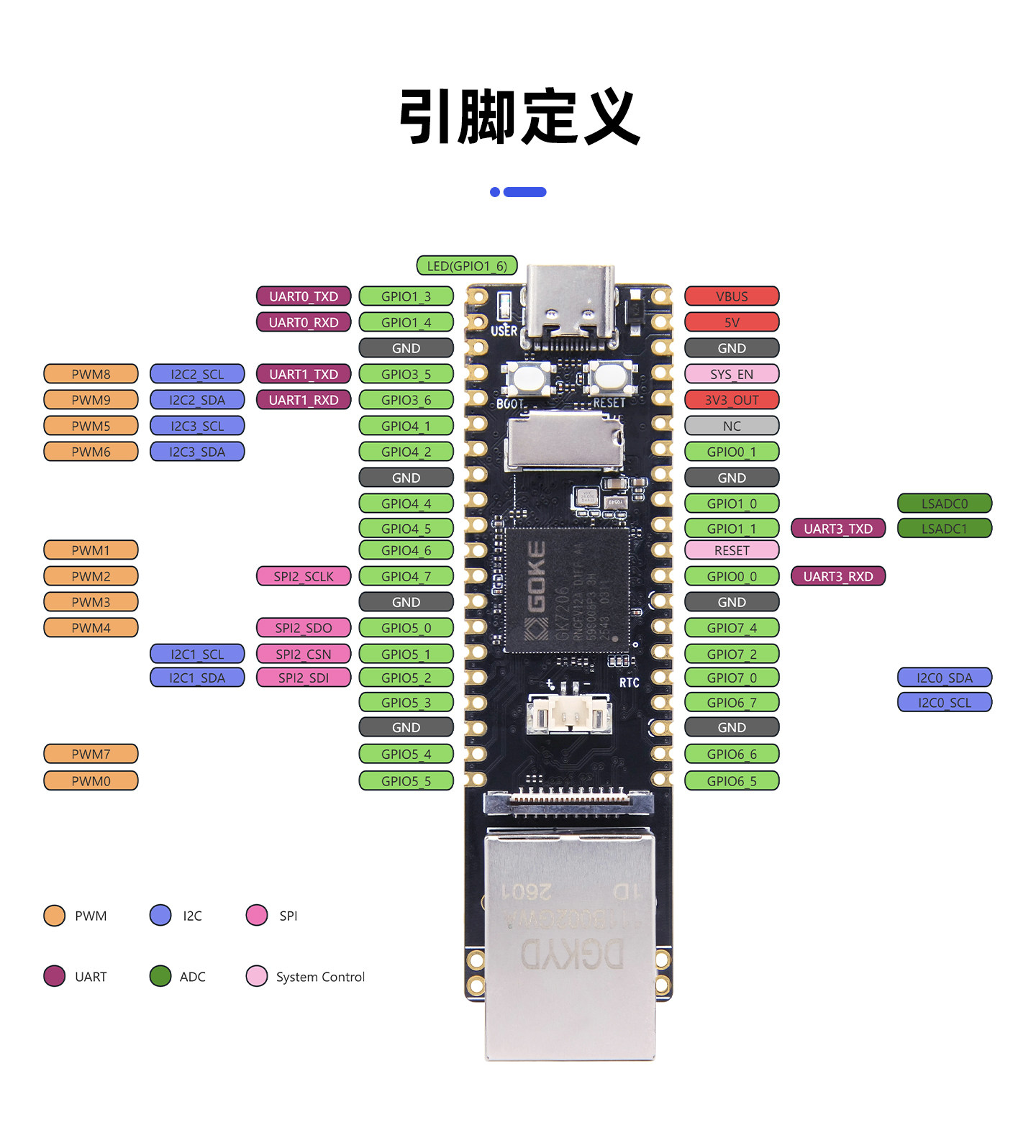
sysfs Interface
Detect SPI Devices
# List available SPI devices in the system
ls /sys/bus/spi/devices/
Expected output:
spi0.0  spi1.0  spi1.1  spi2.0

#spi1.0 = SPI bus 1, chip select 0
# View SPI device information
cat /sys/bus/spi/devices/spi0.0/modaliasExpected output:
spi:dh2228fvUsing the spidev_test Tool
spidev_test is an SPI test tool shipped with the Linux kernel, used to verify that SPI communication works correctly.
Install the spidev_test tool
- Find the ARM cross-compiler path
find . -name "*gcc" | grep binExpected output:
./tools/linux/toolchains/arm-gcc12.2.0-linux-uclibceabi/bin/arm-gcc12.2.0_uClibcng1.0.48-linux-uclibceabi-gcc
./tools/linux/toolchains/arm-gcc12.2.0-linux-uclibceabi/bin/arm-gcc12.2.0-linux-uclibceabi-gcc- Build spidev_test
./tools/linux/toolchains/arm-gcc12.2.0-linux-uclibceabi/bin/arm-gcc12.2.0-linux-uclibceabi-gcc -static ./source/kernel/linux-5.10.y/tools/spi/spidev_test.c -o ./out/spidev_testThe spidev_test executable now appears in the out directory.
- Check the spidev_test format
file spidev_testExpected output:
spidev_test: ELF 32-bit LSB executable, ARM, EABI5 version 1 (SYSV), statically linked, with debug_info, not strippedTip
It must be a program built for a 32-bit ARM Linux system; a different architecture means the cross-compiler was not used.
- Copy the spidev_test file to the board and grant execute permission
chmod +x spidev_testTest 1: 5 MHz, Mode 3, 8-bit, loopback mode
# 5 MHz clock, mode3 (CPOL=1, CPHA=1), 8-bit, enable internal loopback
./spidev_test -D /dev/spidev0.0 -s 5000000 -d 8 -H -O -l
Expected output:
spi mode: 0x23
bits per word: 8
max speed: 5000000 Hz (5000 kHz)
Test 2: 10 MHz, Mode 2, 16-bit, loopback mode
# 10 MHz clock, mode2 (CPOL=1, CPHA=0), 16-bit, enable internal loopback
./spidev_test -v -s 10000000 -b 16 -O -I -D /dev/spidev0.0
Expected output:
spi mode: 0x2
bits per word: 16
max speed: 10000000 Hz (10000 kHz)
TX | FF FF FF FF FF FF 40 00 00 00 00 95 FF FF FF FF FF FF FF FF FF FF FF FF FF FF FF FF FF FF F0 0D  |......@.........................|
RX | 00 00 00 00 00 00 00 00 00 00 00 00 00 00 00 00 00 00 00 00 00 00 00 00 00 00 00 00 00 00 00 00  |................................|
Tip
Loopback mode (the -l parameter) enables the controller's internal loopback — the sent data is returned directly to the receiving end, used to verify that the SPI controller itself is working. Do not enable loopback mode when communicating with an actual peripheral.