
06 - MQ Gas Sensor Application
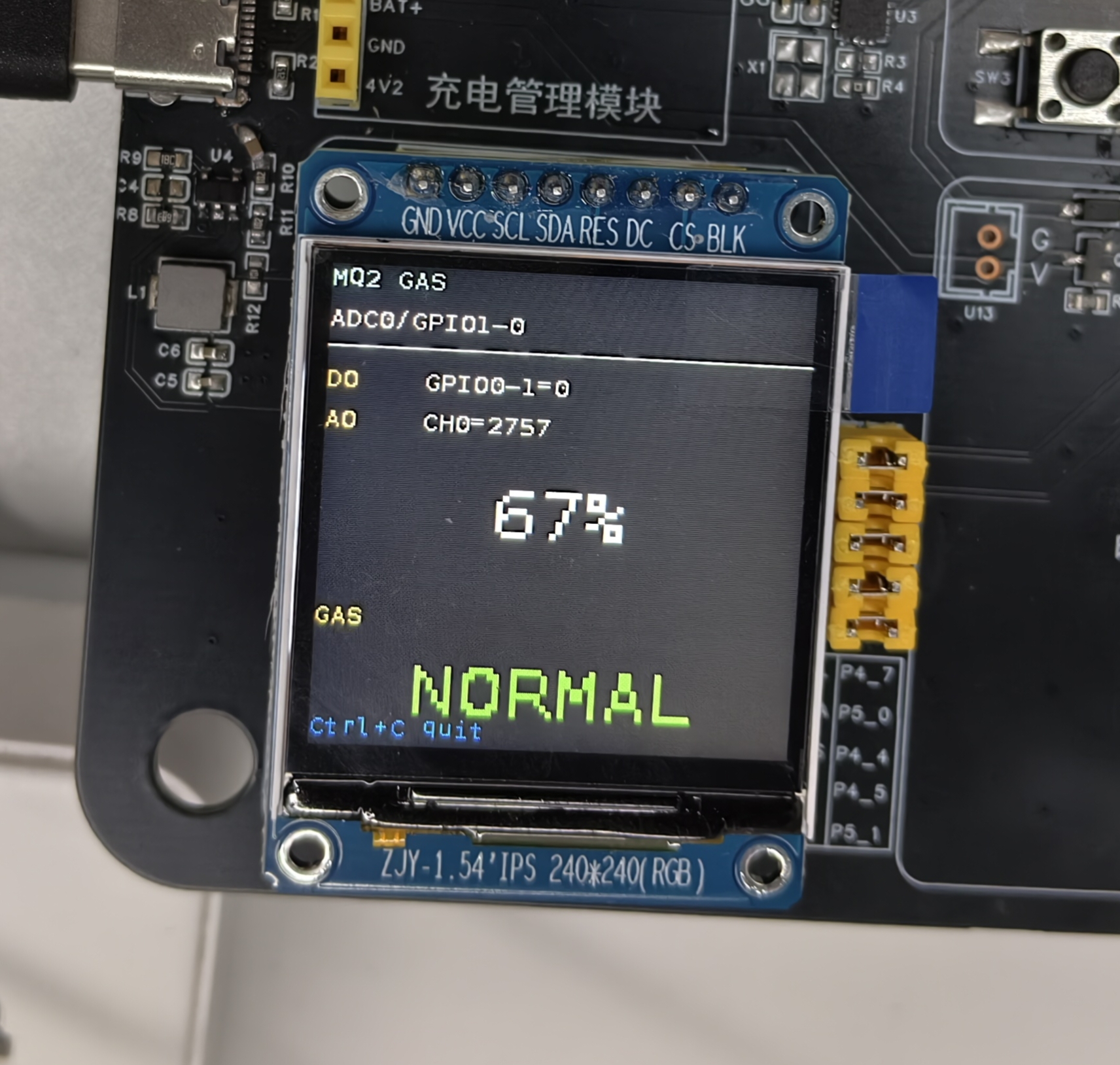
This chapter describes the MQ2 gas sensor application example on the Pico-G1 expansion board — mq_sensor. It demonstrates how to read the sensor's digital output (DO) and analog output (AO) and display the gas concentration and alarm status on a TFT screen. It is a practical example for learning gas sensor monitoring.
The application source code lives in the SDK directory source/app/06_MQ_Sensor/, providing a complete GPIO and ADC reading implementation.
1 Application Overview
1.1 Features
- Dual-mode reading: reads the digital output (DO) and analog output (AO) simultaneously
- Concentration display: shows the gas concentration percentage on a TFT screen
- Alarm monitoring: displays the gas leak alarm status in real time
- Direct ADC access: accesses the LSADC registers directly through
/dev/mem
1.2 Technical Specifications
| Parameter | Value |
|---|---|
Sensor type | MQ2 (smoke / combustible gas / LPG) |
DO interface | GPIO0_1 (digital output) |
AO interface | GPIO1_0/LSADC_CH0 (analog output) |
Supply voltage | 5V (required by the heater) |
ADC resolution | 12-bit (0~4095) |
Refresh interval | 200ms (configurable) |
1.3 Hardware Connection
| Signal | On-board GPIO | Physical pad | Description |
|---|---|---|---|
| DO | GPIO0_1 | iocfg_reg1 @ 0x112C0004 | Digital output (alarm threshold) |
| AO | GPIO1_0 | iocfg_reg20 @ 0x12090000 | Analog output (concentration value) |
| VCC | 5V | — | Power supply (the heater requires 5V) |
| GND | GND | — | Ground |
2 Build and Deployment
2.1 Building the Application
export PATH=$PATH:<SDK>/tools/linux/toolchains/arm-gcc12.2.0-linux-uclibceabi/bin
cd <SDK>/source/app/06_MQ_Sensor
make
2.2 Running the Application
scp mq_sensor root@<board-IP>:/usr/bin/
ssh root@<board-IP> '/usr/bin/mq_sensor'
3 Expected Output
3.1 Console output
/mnt # ./gas_sensor
[mq2] pad 复用:LSADC_CH0 pad (GPIO1_0) -> func4
[mq2] pad 0x12090000 -> 0x00001004
[mq2] 初始化 SPI 屏(/dev/spidev2.0)...
[spi] pad 0x100C0028 -> 0x00001004
[spi] pad 0x100C002C -> 0x00001004
[spi] pad 0x100C0030 -> 0x00001000
[spi] pad 0x100C0020 -> 0x00001005
[spi] pad 0x100C001C -> 0x00001005
[spi] opening /dev/spidev2.0 ...
[spi] spidev opened, fd=3
[spi] spidev mode/bits/speed set (MODE3/8b/24MHz)
[spi] chardev request DC  @ /dev/gpiochip4 line 5 ...
[spi] chardev request RES @ /dev/gpiochip4 line 4 ...
[spi] chardev request CS  @ /dev/gpiochip5 line 1 ...
[spi] chardev-verify: DC=0(expect0) RES=1(expect1) CS=1(expect1)  ==> OK(chardev 真驱动了引脚)
[spi] spi_hal_init done
[tft] init: SLPOUT
[tft] init: SLPOUT +120ms ok
[tft] init: config cmds ok
[tft] init: DISPON
[tft] init: DISPON ok
[tft] init: clear-flush start
[tft] flush #1 start
[tft] flush #1 done
[tft] init: clear-flush done
[mq2] 初始化 MQ2(DO=GPIO0_1, AO=GPIO1_0/LSADC_CH0)...
[mq2] LSADC 寄存器已 mmap @ 0x120A0000 (CH0 走 /dev/mem 绕过驱动)
[mq2] @ DO=GPIO0_1(/dev/gpiochip0 line1) + AO=GPIO1_0/LSADC_CH0(/dev/mem 直读)
[mq2] 采集中,每 200ms 刷新,Ctrl+C 退出。
[mq2] DO=0 AO=2909 (71%)
3.2 TFT screen display
4 Troubleshooting
| Problem | Possible cause | Solution |
|---|---|---|
| ALARM always shown | Threshold potentiometer set too low | Adjust the potentiometer on the module |
| Abnormal concentration value | AO read failure | Check the LSADC CH0 configuration |
| Sensor not responding | Insufficient power supply | Confirm the 5V supply |