
02 - TFT Display Application
This chapter describes the TFT display application example on the Pico-G1 expansion board — tft_display. It demonstrates how to drive an ST7789 TFT color screen over the SPI interface for high-resolution color graphics. It is an advanced example for learning high-speed SPI communication and graphics programming, covering the full technology stack from low-level SPI operations to graphics rendering.
The application source code lives in the SDK directory source/app/02_TFT_display/, providing a complete SPI character-device implementation and ST7789 driver — an important reference for learning embedded graphics programming.
1 Application Overview
1.1 Features
- High-speed SPI communication: demonstrates high-speed data transfer through the Linux SPI character-device interface
- TFT driver: complete ST7789 driver implementation (initialization, drawing, refresh)
- Color graphics display: high-resolution display in RGB565 format (65536 colors)
- Graphics rendering: graphics functions such as pixel drawing, rectangle filling, and text rendering
- Real-time info: displays uptime, CPU status, and other live system information
- Font support: built-in 8×16 ASCII bitmap font (0x20~0x7E)
1.2 Technical Specifications
| Parameter | Value |
|---|---|
TFT model | ST7789, 240×240 pixels |
Communication interface | SPI (SPI2, /dev/spidev2.0) |
SPI mode | MODE3 (CPOL=1, CPHA=1) |
SPI speed | 24MHz (maximum) |
Color format | RGB565 (16-bit, 65536 colors) |
Framebuffer size | 240×240×2 = 115200 bytes (113KB) |
Font size | 8×16 pixel ASCII font |
Refresh interval | 1 second (configurable) |
1.3 Test Case List
| index | Name | Test command | Expected result (success) | Possible causes of failure |
|---|---|---|---|---|
| 1 | Welcome screen | ./tft_display | Color blocks and welcome message are shown | SPI connection failure, wrong TFT address |
| 2 | Continuous refresh | ./tft_display (no arguments) | After the welcome screen, system info refreshes every second | Same as above |
| 3 | Graphics test | Color rectangles and text displayed | All colors render correctly | Wrong color format, framebuffer error |
1.4 Directory Structure
source/app/02_TFT_display/
├── Makefile              # Build script
├── main.c                # Main program
├── spi_hal.c             # SPI HAL layer implementation
├── spi_hal.h             # SPI HAL layer header
├── gpio_hal.c            # GPIO HAL layer implementation
├── gpio_hal.h            # GPIO HAL layer header
├── st7789.c              # ST7789 driver implementation
├── st7789.h              # ST7789 driver header
├── font8x16.h            # 8×16 ASCII bitmap font
└── README.md             # Documentation
2 Hardware Connection
2.1 Pin Definition
| Signal | On-board GPIO | Controller / node | Description |
|---|---|---|---|
| SCK | GPIO4_7 | SPI2 → /dev/spidev2.0 | SPI clock |
| MOSI | GPIO5_0 | SPI2 → /dev/spidev2.0 | SPI master output |
| CS | GPIO5_1 | /dev/gpiochip5 line1 | Chip select (manual framing) |
| DC | GPIO4_5 | /dev/gpiochip4 line5 | Data/command select |
| RES | GPIO4_4 | /dev/gpiochip4 line4 | Reset |
| VCC | 3.3V | — | Power supply |
| GND | GND | — | Ground |
2.2 Hardware Circuit
Standard SPI TFT wiring:
     Pico-G1                   ST7789 TFT Module
  ┌───────────┐              ┌──────────────┐
  │           │              │              │
  │ GPIO4_7 ──┼────── SCK ──┤ SCK          │
  │           │              │              │
  │ GPIO5_0 ──┼────── MOSI ──┤ SDA/MOSI     │
  │           │              │              │
  │ GPIO5_1 ──┼────── CS ───┤ CS           │
  │           │              │              │
  │ GPIO4_5 ──┼────── DC ───┤ DC/RS        │
  │           │              │              │
  │ GPIO4_4 ──┼────── RES ──┤ RES/RESET    │
  │           │              │              │
  │    3.3V ──┼─────────────┤ VCC          │
  │           │              │              │
  │     GND ──┼─────────────┤ GND          │
  │           │              │              │
  └───────────┘              └──────────────┘
Pin functions
- SCK/MOSI: SPI data lines, driven by the SPI2 controller
- CS: chip select, active low, controlled manually via GPIO
- DC: data/command select, high = data, low = command
- RES: reset signal, active low
- VCC: supply voltage, 3.3V (some modules support 5V)
2.3 Pin Multiplexing
Pin multiplexing that needs to be configured:
| pad | Physical address | Value | Description |
|---|---|---|---|
| SCK (GPIO4_7) | 0x100C0028 | 0x1004 | func4 = SPI2_SCLK |
| MOSI (GPIO5_0) | 0x100C002C | 0x1004 | func4 = SPI2_SDO |
| CS (GPIO5_1) | 0x100C0030 | 0x1000 | func0 = GPIO (manual framing) |
| DC (GPIO4_5) | 0x100C0020 | 0x1005 | func5 = GPIO (default JTAG_TDO) |
| RES (GPIO4_4) | 0x100C001C | 0x1005 | func5 = GPIO (default JTAG_TDI) |
JTAG pin conflict
GPIO4_4 and GPIO4_5 default to their JTAG function and must be manually configured as GPIO. Without this configuration, the SPI display will not work.
3 Build and Deployment
3.1 Prerequisites
Before building this application, make sure the following preparations are complete:
- SDK environment ready: set up the cross-compilation toolchain and SDK by following Development Environment Setup
- Kernel configuration confirmed: make sure the kernel has SPI driver support enabled
- Hardware connected: the TFT module is correctly wired to the corresponding pins
3.2 Building the Application
# Set the toolchain path
export PATH=$PATH:<SDK>/tools/linux/toolchains/arm-gcc12.2.0-linux-uclibceabi/bin

# Enter the example directory
cd <SDK>/source/app/02_TFT_display

# Build
make

# Clean
make clean
After a successful build, the executable tft_display is generated in the current directory.
3.3 Deploying to the Board
# Transfer to the development board with SCP
scp tft_display root@<board-IP>:/usr/bin/

# Or download via TFTP
tftp -g -r tft_display <board-IP>
3.4 Running the Application
# Add execute permission
chmod +x /usr/bin/tft_display

# Run the TFT display example
/usr/bin/tft_display
Once started, the TFT screen shows a color welcome screen; after 2 seconds it starts displaying real-time system information. Press Ctrl+C to exit.
3.5 Expected Output
Console output
/mnt # ./spi_display
[spi] init ST7789 @ /dev/spidev2.0 ...
[spi] pad 0x100C0028 -> 0x00001004
[spi] pad 0x100C002C -> 0x00001004
[spi] pad 0x100C0030 -> 0x00001000
[spi] pad 0x100C0020 -> 0x00001005
[spi] pad 0x100C001C -> 0x00001005
[spi] opening /dev/spidev2.0 ...
[spi] spidev opened, fd=3
[spi] spidev mode/bits/speed set (MODE3/8b/24MHz)
[spi] chardev request DC  @ /dev/gpiochip4 line 5 ...
[spi] chardev request RES @ /dev/gpiochip4 line 4 ...
[spi] chardev request CS  @ /dev/gpiochip5 line 1 ...
[spi] chardev-verify: DC=0(expect0) RES=1(expect1) CS=1(expect1)  ==> OK(chardev 真驱动了引脚)
[spi] spi_hal_init done
[tft] >>> st7789_init()
[tft] init: SLPOUT
[tft] init: SLPOUT +120ms ok
[tft] init: config cmds ok
[tft] init: DISPON
[tft] init: DISPON ok
[tft] init: clear-flush start
[tft] flush #1 start
[tft] flush #1 done
[tft] init: clear-flush done
[tft] <<< st7789_init() returned
[spi] 初始化成功,开始显示。
[tft] flush #2 start
[tft] flush #2 done
[tft] flush #3 start
[tft] flush #3 done
TFT screen display
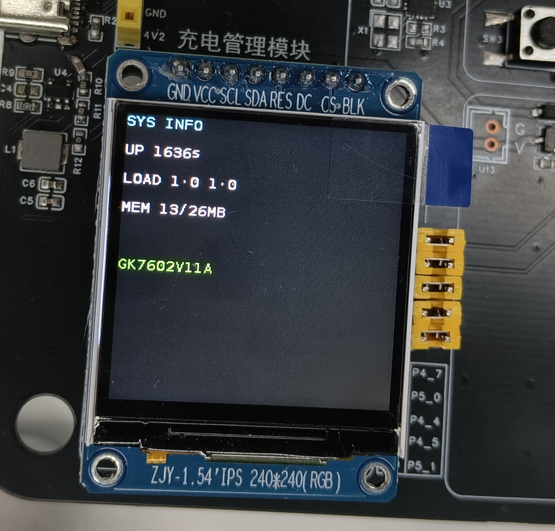
Fixed and variable parts
- Fixed part: the display format and layout (matches the fixed code)
- Variable part: the system uptime values (updated on every refresh)
4 Internal Execution Logic
4.1 Application Architecture
This application uses a layered design consisting of a hardware abstraction layer, a driver layer, and an application layer:
// Application layer (main.c)
int main(int argc, char *argv[])
{
    // 1. Initialize pin multiplexing
    padmux_init();

    // 2. Initialize the SPI HAL layer
    spi_init();

    // 3. Initialize GPIO (DC/RES/CS)
    gpio_init();

    // 4. Initialize the TFT driver
    st7789_init();

    // 5. Show the welcome screen
    display_welcome();
    sleep(2);

    // 6. Main loop refreshing system information
    while (1) {
        st7789_clear();
        display_system_info();
        st7789_refresh();
        sleep(1);
    }

    return 0;
}
4.2 SPI HAL Layer Implementation
The SPI HAL layer wraps the Linux SPI character-device operations:
// SPI initialization
int spi_init(void)
{
    int fd = open("/dev/spidev2.0", O_RDWR);
    if (fd < 0) {
        perror("打开 SPI 设备失败");
        return -1;
    }

    // Set the SPI mode to MODE3
    uint8_t mode = SPI_MODE_3;
    ioctl(fd, SPI_IOC_WR_MODE, &mode);

    // Set the number of bits per transfer to 8
    uint8_t bits = 8;
    ioctl(fd, SPI_IOC_WR_BITS_PER_WORD, &bits);

    // Set the maximum SPI speed
    uint32_t speed = 24000000;  // 24MHz
    ioctl(fd, SPI_IOC_WR_MAX_SPEED_HZ, &speed);

    return fd;
}

// SPI data transfer
int spi_transfer(uint8_t *tx_data, uint8_t *rx_data, uint32_t length)
{
    struct spi_ioc_transfer tr = {
        .tx_buf = (unsigned long)tx_data,
        .rx_buf = (unsigned long)rx_data,
        .len = length,
        .speed_hz = 24000000,
        .bits_per_word = 8,
        .delay_usecs = 0,
    };

    return ioctl(spi_fd, SPI_IOC_MESSAGE(1), &tr);
}
4.3 ST7789 Driver Implementation
The ST7789 driver implements full TFT screen control:
// TFT initialization sequence
void st7789_init(void)
{
    // Hardware reset
    gpio_set_value(RES_GPIO, 0);
    usleep(10000);
    gpio_set_value(RES_GPIO, 1);
    usleep(10000);

    // Send initialization commands
    st7789_write_command(0x11);  // SLPOUT (exit sleep mode)
    usleep(120000);                // wait 120ms

    // MADCTL (page address order)
    st7789_write_command(0x36);
    st7789_write_data(0x00);

    // COLMOD (pixel format set)
    st7789_write_command(0x3A);
    st7789_write_data(0x05);     // 16-bit/pixel

    // ... other initialization commands

    st7789_write_command(0x21);  // INVON (display inversion on)
    st7789_write_command(0x29);  // DISPON (display on)

    usleep(20000);                // wait for the display to turn on

    st7789_clear();
    st7789_refresh();
}

// Send a command
void st7789_write_command(uint8_t cmd)
{
    gpio_set_value(DC_GPIO, 0);   // DC = 0, command mode
    gpio_set_value(CS_GPIO, 0);   // CS = 0, chip select active

    spi_transfer(&cmd, NULL, 1);

    gpio_set_value(CS_GPIO, 1);   // CS = 1, chip select inactive
}

// Send data
void st7789_write_data(uint8_t *data, uint32_t length)
{
    gpio_set_value(DC_GPIO, 1);   // DC = 1, data mode
    gpio_set_value(CS_GPIO, 0);   // CS = 0, chip select active

    spi_transfer(data, NULL, length);

    gpio_set_value(CS_GPIO, 1);   // CS = 1, chip select inactive
}
4.4 Graphics Rendering
The driver layer provides basic graphics rendering:
// Set a pixel
void st7789_set_pixel(int x, int y, uint16_t color)
{
    if (x < 0 || x >= TFT_WIDTH || y < 0 || y >= TFT_HEIGHT)
        return;

    int index = (y * TFT_WIDTH + x) * 2;
    framebuffer[index] = color >> 8;      // high byte
    framebuffer[index + 1] = color & 0xFF; // low byte
}

// Clear the screen
void st7789_clear(void)
{
    memset(framebuffer, 0, sizeof(framebuffer));
}

// Refresh the display
void st7789_refresh(void)
{
    // Set the column address range
    st7789_write_command(0x2A);  // CASET
    uint8_t col_data[] = {0, 0, 0, (TFT_WIDTH - 1) & 0xFF};
    st7789_write_data(col_data, 4);

    // Set the row address range
    st7789_write_command(0x2B);  // RASET
    uint8_t row_data[] = {0, 0, 0, (TFT_HEIGHT - 1) & 0xFF};
    st7789_write_data(row_data, 4);

    // Write the framebuffer data
    st7789_write_command(0x2C);  // RAMWR
    st7789_write_data(framebuffer, sizeof(framebuffer));
}
5 Key Programming Points
5.1 SPI Timing Control
Characteristics of SPI MODE3:
- CPOL = 1: the clock idles high
- CPHA = 1: data is sampled on the falling clock edge
5.2 RGB565 Color Format
RGB565 is a 16-bit color format:
Bit layout: RRRRRGGG GGGBBBBB
          ↑5-bit red↑ ↑6-bit green↑↑5-bit blue↑

Examples:
- Red   (0xF800): 11111 000000 00000
- Green (0x07E0): 00000 111111 00000
- Blue  (0x001F): 00000 000000 11111
- White (0xFFFF): 11111 111111 11111
5.3 Framebuffer Management
Framebuffer layout:
- 240×240 pixels, 2 bytes per pixel
- Total size: 240 × 240 × 2 = 115,200 bytes
- Byte order: big-endian (MSB first)
Access method:
// Compute the framebuffer offset of pixel (x,y)
int index = (y * TFT_WIDTH + x) * 2;

// Write pixel data (big-endian)
framebuffer[index] = color >> 8;      // high byte
framebuffer[index + 1] = color & 0xFF; // low byte
5.4 High-Speed Refresh Optimization
Chunked transfer:
// The TX FIFO is < 128 bytes, so data must be transferred in chunks
#define CHUNK_SIZE 16

void st7789_refresh(void)
{
    // ... set the address range ...

    gpio_set_value(DC_GPIO, 1);   // data mode
    gpio_set_value(CS_GPIO, 0);   // chip select active

    // Transfer the framebuffer data in chunks
    for (int i = 0; i < sizeof(framebuffer); i += CHUNK_SIZE) {
        int chunk_len = min(CHUNK_SIZE, sizeof(framebuffer) - i);
        spi_transfer(&framebuffer[i], NULL, chunk_len);
        usleep(100);  // breather between chunks to avoid FIFO overflow
    }

    gpio_set_value(CS_GPIO, 1);   // chip select inactive
}
6 Code Customization
6.1 Changing the SPI Speed
Edit the SPI speed parameter in spi_hal.c:
uint32_t speed = 24000000;  // 24MHz (maximum)
// uint32_t speed = 12000000;  // 12MHz (stable)
// uint32_t speed = 8000000;   // 8MHz (compatible)
Choosing the SPI speed
- 24MHz: highest speed, may be unstable
- 12MHz: recommended, stable and reliable
- 8MHz: best compatibility, suitable for long wires
6.2 Changing the Resolution
Other resolutions (e.g. 135×240) are supported:
// Modify st7789.h
#define TFT_WIDTH   135
#define TFT_HEIGHT  240

// Adjust the corresponding parameters in the initialization sequence
st7789_write_command(0x2A);  // CASET
uint8_t col_data[] = {0, 0, 0, (TFT_WIDTH - 1) & 0xFF};
st7789_write_data(col_data, 4);
6.3 Adding Graphics Functions
Add more graphics functions:
// Draw a horizontal line
void st7789_draw_hline(int x1, int x2, int y, uint16_t color)
{
    for (int x = x1; x <= x2; x++)
        st7789_set_pixel(x, y, color);
}

// Draw a vertical line
void st7789_draw_vline(int x, int y1, int y2, uint16_t color)
{
    for (int y = y1; y <= y2; y++)
        st7789_set_pixel(x, y, color);
}

// Draw a rectangle
void st7789_draw_rect(int x1, int y1, int x2, int y2, uint16_t color)
{
    st7789_draw_hline(x1, x2, y1, color);
    st7789_draw_hline(x1, x2, y2, color);
    st7789_draw_vline(x1, y1, y2, color);
    st7789_draw_vline(x2, y1, y2, color);
}
7 Troubleshooting
| Problem | Possible cause | Solution |
|---|---|---|
| Screen stays dark | SPI connection failure, insufficient power | Check wiring, confirm the supply voltage |
| Garbled or corrupted screen | Wrong initialization sequence, SPI speed too high | Check init parameters, lower the SPI speed |
| Wrong colors | Wrong RGB565 format, wrong byte order | Check the color format conversion, confirm byte order |
| Partial display anomalies | Wrong address range settings | Check the CASET/RASET parameters |
| Slow refresh | Unsuitable chunk size, speed too low | Adjust the chunk size, raise the SPI speed |
| White screen, no display | Contrast setting, display not turned on | Adjust contrast, confirm the DISPON command |
8 Advanced Extensions
8.1 Image Display
Support bitmap-format images:
// Display an RGB565 image
void st7789_draw_image(int x, int y, int width, int height, const uint16_t *image)
{
    for (int row = 0; row < height; row++) {
        for (int col = 0; col < width; col++) {
            st7789_set_pixel(x + col, y + row, image[row * width + col]);
        }
    }
}
8.2 Partial Refresh
Refresh only the changed region to improve efficiency:
// Partial refresh
void st7789_refresh_partial(int x1, int y1, int x2, int y2)
{
    // Set the partial refresh range
    st7789_write_command(0x2A);  // CASET
    uint8_t col_data[] = {x1 >> 8, x1 & 0xFF, x2 >> 8, x2 & 0xFF};
    st7789_write_data(col_data, 4);

    st7789_write_command(0x2B);  // RASET
    uint8_t row_data[] = {y1 >> 8, y1 & 0xFF, y2 >> 8, y2 & 0xFF};
    st7789_write_data(row_data, 4);

    // Write the partial framebuffer data
    st7789_write_command(0x2C);  // RAMWR
    // ... write the data of the partial region ...
}
8.3 Double Buffering
Use double buffering to avoid flicker:
uint16_t framebuffer_front[TFT_WIDTH * TFT_HEIGHT];
uint16_t framebuffer_back[TFT_WIDTH * TFT_HEIGHT];

void st7789_swap_buffers(void)
{
    // Swap the front and back buffer pointers
    uint16_t *temp = framebuffer_front;
    framebuffer_front = framebuffer_back;
    framebuffer_back = temp;

    // Refresh the front buffer to the display
    st7789_refresh();
}