
HOME
Shop
  • English
  • 简体中文
HOME
Shop
  • English
  • 简体中文
  • Product Series

    • FPGA+ARM

      • GM-3568JHF

        • Introduction

          • GM-3568JHF Introduction
        • Quick Start

          • Preface
          • Environment Setup
          • Compilation Notes
          • Flashing Guide
          • Debugging Tools
          • Software Update
          • Viewing System Information
          • Test Commands
          • Application Compilation
          • Source Code Access
        • Peripherals & Interfaces

          • USB
          • Display and Touch
          • Ethernet
          • WIFI
          • Bluetooth
          • TF-Card
          • Audio
          • Serial Port
          • CAN
          • RTC
        • Application Development

          • UART Read/Write Demo
          • Key Detection Demo
          • LED Blink Demo
          • MIPI Screen Detection Demo
          • Read USB Device Information Demo
          • FAN Detection Demo
          • FPGA FSPI Communication Demo
          • FPGA DMA Read/Write Demo
          • GPS Debugging Demo
          • Ethernet Test Demo
          • RS485 Read/Write Demo
          • FPGA I2C Read/Write Demo
          • PN532 NFC Card-Reading Demo
          • TF Card Read/Write Demo
        • QT Development

          • ARM64 Cross-Compiler Environment Setup
          • Adding a QT Program to Boot Auto-Start
        • RKNN_NPU Development

          • RK3568 NPU Overview
          • Development Environment Setup
          • Run the Official YOLOv5 Example
        • FPGA Development

          • ARM and FPGA Communication
          • FPGA Development Manual
        • Others

          • Modifying the Root Filesystem
          • System Auto-Start Services
        • Downloads

          • Downloads
      • MB-E30P

        • Introduction

          • MB-E30P Introduction
        • Quick Start

          • Preface
          • Environment Setup
          • Compilation Instructions
          • Flashing Guide
          • Debugging Tools
          • Software Update
          • Viewing Information
          • Test Commands
          • Application Compilation
          • Source Code Acquisition
        • Peripherals & Interfaces

          • USB
          • Display and Touch
          • Ethernet
          • WIFI
          • Bluetooth
          • TF-Card
          • Audio
          • RTC
        • Application Development

          • Key Detection Demo
          • LED Blink Demo
          • MIPI Screen Detection Demo
          • Read USB Device Information Demo
          • FAN Detection Demo
          • FPGA FSPI Communication Demo
          • FPGA DMA Read/Write Demo
          • Ethernet Test Demo
          • FPGA IIC Read/Write Demo
          • PN532 NFC Card Reading Demo
          • TF Card Read/Write Demo
        • QT Development

          • ARM64 Cross-Compiler Environment Setup
          • Adding a QT Program to the Boot Auto-Start Service
        • RKNN_NPU Development

          • RK3568 NPU Overview
          • Development Environment Setup
          • Run the Official YOLOv5 Example
          • Model Conversion In Detail
          • Run Custom Models on the Board
        • FPGA Development

          • ARM and FPGA Communication
          • FPGA Development Manual
        • Others

          • Modifying the Root Filesystem
          • System Auto-Start Service
        • Downloads

          • Downloads
    • ShimetaPi

      • M4-R1

        • Introduction

          • M4-R1 Introduction
        • Quick Start

          • OpenHarmony Overview
          • Image Burning
          • Application Development Quick Start
          • Device Development Quick Start
        • Application Development

          • ArkUI

            • ArkTS Language Overview
            • UI Components - Row Container Introduction
            • UI Components - Column Container Introduction
            • UI Components - Text Component
            • UI Components - Toggle Component
            • UI Components - Slider Component
            • UI Components - Animation Component & Transition Component
          • Documentation

            • OpenHarmony Official Materials
          • Development Notes

            • Full-SDK Replacement Tutorial
            • Introducing and Using Third-Party Libraries
            • HDC Debugging
            • Restore Factory Mode via Command Line
            • Upgrade App to System Permission
          • First App

            • Build Your First ArkTS Application - HelloWorld
          • Demos

            • Serial-Debug-Assistant Application Demo
            • Writing-Board Application Demo
            • Digital Clock Application Demo
            • Wi-Fi Information Acquisition Application Demo
        • Device Development

          • Ubuntu Development

            • Environment Setup
            • Download Source Code
            • Compile Source Code
          • DevEco Device Tool

            • Tool Introduction
            • Development Environment Construction
            • Import the SDK
            • HUAWEI DevEco Tool Function Introduction
        • Kernel Peripherals & Interfaces

          • Guide
          • Device Tree Introduction
          • NAPI Introduction
          • ArkTS Introduction
          • NAPI Development Hands-on Demo
          • GPIO Introduction
          • I2C Communication
          • SPI Communication
          • PWM Control
          • UART Communication
          • TF Card (MicroSD)
          • Screen (Display)
          • Touch
          • Ethernet
          • M.2 SSD
          • Audio
          • WIFI & BT
          • Camera
        • Downloads

          • Downloads
      • M5-R1

        • Introduction

          • M5-R1 Development Docs
        • Quick Start

          • Image Burning
          • Environment Setup
          • Download Source Code
        • Peripherals & Interfaces

          • Raspberry Pi Interfaces
          • GPIO Interface
          • I2C Interface
          • SPI Communication
          • PWM Control
          • Serial Port Communication
          • TF Card
          • Display
          • Touch
          • Audio
          • RTC
          • Ethernet
          • M.2
          • MINI-PCIE
          • Camera
          • WIFI & BT
        • Downloads

          • Downloads
      • Pico-G1

        • Product Overview

          • Product Introduction
          • SDK Version Information
        • Quick Start

          • Development Environment Setup
          • Image Build
          • Image Flashing
          • System Login
          • Network Configuration
          • File Transfer
          • SDK Directory Structure
          • Deploying Your First Application
          • Deploying Your First Driver
          • Mounting an SD Card
        • Peripherals & Interfaces

          • GPIO Control
          • UART Serial Communication
          • I2C Communication
          • SPI Communication
        • MPP Media Development

          • MPP Media Processing Software
          • Image Processing Chain
          • Video Input
          • Image Encoding
        • NPU & AI

          • NPU Driver and Runtime Library Architecture
          • .xmm Model Loading
          • SVP Video Processing
          • AI Noise Reduction (AI_NR)
        • Application Samples

          • Encryption/Decryption Application
          • ADC Acquisition Application
          • Low-Power Application
          • Audio Processing Application
          • Video Encoding Application
          • Video Input Application
          • Video Graphics Subsystem (VGS) Application
          • 08 Region Overlay Application
          • 09 Intelligent Video Engine Application
          • 10 UVC Webcam Application
          • 11 All-in-One Quickstart Application
          • 12 FPN Correction Application
          • 13 Regional Motion Detection Application
          • 14 MTCNN Face Detection Application
        • Expansion Board Peripheral Examples

          • 00 - Pico Expansion Board Peripheral Examples Overview
          • 01 - OLED Display Application
          • 02 - TFT Display Application
          • 03 - MPU6050 Gyroscope Application
          • 04 - ADC Acquisition Application
          • 05 - Passive Buzzer Application
          • 06 - MQ Gas Sensor Application
          • 07 - GPS Positioning Application
          • 08 - SHT20 Temperature & Humidity Application
          • 09 - Ultrasonic Ranging Application
          • 10 - SpO2 Sensor Application
          • 11 - DC Motor Control Application
          • 12 - Servo Control Application
    • OpenHarmony

      • SC-3568HA

        • Introduction

          • SC-3568HA Overview
        • Quick Start Guide

          • OpenHarmony Overview
          • Image Flashing
          • Setting Up the Development Environment
          • Hello World Application and Deployment
        • Application Development

          • ArkUI

            • Introduction to ArkTS Language
            • Introduction to UI Components and Practical Applications (Part 1)
            • Introduction to UI Components and Practical Applications (Part 2)
            • Introduction to UI Components and Practical Applications (Part 3)
          • Expand

            • Getting Started Guide
            • Referencing and Using Third-Party Libraries
            • Application Compilation and Deployment
            • Command-Line Factory Reset
            • System Debugging -- HDC Debugging
            • APP Stability Testing
            • Chapter 7 Application Testing
        • Device Development

          • Environment Setup
          • Download Source Code
          • Compiling Source Code
        • Peripheral And Interface

          • Raspberry Pi interface
          • GPIO Interface
          • I2C Interface
          • SPI communication
          • PWM (Pulse Width Modulation) control
          • Serial port communication
          • TF Card
          • Display Screen
          • Touch
          • Audio
          • RTC
          • Ethernet
          • M.2
          • MINI-PCIE
          • Camera
          • WIFI&BT
          • Raspberry Pi expansion board
        • Downloads

          • Downloads
      • M-K1HSE

        • Introduction

          • M-K1HSE Introduction
        • Quick Start

          • Development environment construction
          • Source code acquisition
          • Compilation Notes
          • Burning Guide
        • Application Development

          • Application Development Environment Setup
          • First Application - Hello World
        • Peripherals and interfaces

          • 01 Audio
          • 02 RS485
          • 03 Display
        • System customization development

          • System transplant
          • System customization
          • Driver Development
          • System Debugging
          • OTA Update
        • Downloads

          • Downloads
    • HVS Camera

      • Quick Start

        • SDK Overview
        • Downloads
        • Your First C++ Program
        • Python Data Analysis
        • MultiVision Studio
      • Development

        • Programming Guides

          • Open Camera
          • Read Events
          • Recording & Replay
          • Event Processing (Denoising)
          • Display & Visualization
          • Tuning
          • Capture APS Image
        • Toolkit SDK

          • Hybrid Vision Toolkit
          • Quick Start
          • C++ API
          • Python API
        • Algorithm

          • Hybrid Vision Algo
          • Hybrid Vision Algo API
          • Windows Algo SDK
        • Samples Overview
        • Applications
      • Fundamentals

        • Event Camera Fundamentals
        • HVS Hybrid Vision
        • Event Visualization
        • Data Formats Reference
        • Glossary
        • Bias & Tuning
        • Video Tutorials
      • USB Cameras

        • HVS Camera Quick Start
        • Networking Capabilities

          • HVS Camera System Architecture
          • EVS Network Server
          • EVS Time Sync
          • Web Window
        • HVS Camera Compatibility Matrix
        • FAQ & Troubleshooting Guide
        • Products

          • CF-NRS1 (Lingguang No.1 Hybrid Vision Camera)
      • MIPI Modules

        • MIPI Module Quick Start
        • Carrier Boards

          • RDK X5 Carrier Board Adaptation
          • Raspberry Pi Carrier Board Adaptation
          • Digua Pi Carrier Board Adaptation
          • ShimeTai Board Carrier Board Adaptation
        • MIPI Module Compatibility Matrix
        • Products

          • EVS_003 Sensor Module
    • AI-model

      • 1684XB-32T

        • Introduction

          • AIBOX-1684XB-32 Introduction
        • Quick Start

          • First Use
          • Network Configuration
          • Disk Usage
          • Memory Allocation
          • Fan Control Strategy
          • Firmware Upgrade
          • Cross Compilation
          • Model Quantization
        • Application Development

          • Development Overview

            • Sophgo SDK Development
            • Sophgo Demo Introduction
          • Large Language Models

            • Deploying Llama3 Example
            • Sophon LLM_api_server Development
            • Deploying MiniCPM-V-2_6
            • Qwen-2-5-VL Image and Video Recognition Demo
            • Qwen3-chat Demo
            • Qwen3-Qwen Agent-MCP Development
            • Qwen3-langchain-AI Agent
          • Deep Learning

            • ResNet (Image Classification)
            • LPRNet (License Plate Recognition)
            • SAM (General Image Segmentation Foundation Model)
            • YOLOv5 (Object Detection)
            • OpenPose (Human Keypoint Detection)
            • PP-OCR (Optical Character Recognition)
        • Downloads

          • Downloads
      • 1684X-416T

        • Introduction

          • AIBOX-1684X-416 Introduction
        • Demo Quick Guide

          • ShimeTai Intelligent Monitoring Demo Quick Usage Guide
      • RDK-X5

        • Introduction

          • RDK-X5 Hardware Introduction
        • Quick Start

          • RDK-X5 Quick Start
        • Application Development

          • AI Online Model Development

            • Experiment 01 - Access Volcengine Doubao AI
            • Experiment 02 - Image Analysis
            • Experiment 03 - Multimodal Visual Analysis & Localization
            • Experiment 04 - Multimodal Image-Text Comparison
            • Experiment 05 - Multimodal Document/Table Analysis
            • Experiment 06 - Camera-based AI Visual Analysis
          • Large Language Models

            • Experiment 01 - Speech Recognition
            • Experiment 02 - Voice Conversation
            • Experiment 03 - Multimodal Image Analysis - Voice
            • Experiment 04 - Multimodal Image Comparison - Voice
            • Experiment 05 - Multimodal Document Analysis - Voice
            • Experiment 06 - Multimodal Vision Application - Voice
          • ROS2 Basics

            • Experiment 01 - Environment Setup
            • Experiment 02 - Create & Build a Workspace Package
            • Experiment 03 - Run ROS2 Topic Communication Node
            • Experiment 04 - ROS2 Camera Application
          • 40-pin IO Development

            • Experiment 01 - GPIO Output (LED Blink)
            • Experiment 02 - GPIO Input
            • Experiment 03 - Button-controlled LED
            • Experiment 04 - PWM Output
            • Experiment 05 - Serial Output
            • Experiment 06 - I2C Experiment
            • Experiment 07 - SPI Experiment
          • USB Module Usage

            • Experiment 01 - USB Voice Module Usage
            • Experiment 02 - Sound Source Localization Module
          • Machine Vision Practice

            • Experiment 01 - Open USB Camera
            • Experiment 02 - Color Recognition
            • Experiment 03 - Gesture Recognition
            • Experiment 04 - YOLOv5 Object Detection
      • RDK-S100

        • Introduction

          • RDK-S100 Hardware Introduction
        • Quick Start

          • RDK-S100 Quick Start
        • Application Development

          • AI Online Model Development

            • Experiment 01 - Access Volcengine Doubao AI
            • Experiment 02 - Image Analysis
            • Experiment 03 - Multimodal Visual Analysis & Localization
            • Experiment 04 - Multimodal Image-Text Comparison
            • Experiment 05 - Multimodal Document/Table Analysis
            • Experiment 06 - Camera-based AI Visual Analysis
          • Large Language Models

            • Experiment 01 - Speech Recognition
            • Experiment 02 - Voice Conversation
            • Experiment 03 - Multimodal Image Analysis - Voice
            • Experiment 04 - Multimodal Image Comparison - Voice
            • Experiment 05 - Multimodal Document Analysis - Voice
            • Experiment 06 - Multimodal Vision Application - Voice
          • ROS2 Basics

            • Experiment 01 - Environment Setup
            • Experiment 02 - Create & Build a Workspace Package
            • Experiment 03 - Run ROS2 Topic Communication Node
            • Experiment 04 - ROS2 Camera Application
          • 40-pin IO Development

            • Experiment 01 - GPIO Output (LED Blink)
            • Experiment 02 - GPIO Input
            • Experiment 03 - Button-controlled LED
            • Experiment 04 - PWM Output
            • Experiment 05 - Serial Output
            • Experiment 06 - I2C Experiment
            • Experiment 07 - SPI Experiment
          • USB Module Usage

            • Experiment 01 - USB Voice Module Usage
            • Experiment 02 - Sound Source Localization Module
          • Machine Vision Practice

            • Experiment 01 - Open USB Camera
            • Experiment 02 - Image Processing Basics
            • Experiment 03 - Object Detection
            • Experiment 04 - Image Segmentation
      • RK1828

        • Introduction

          • M5-182X-A1 AI Edge Box - Product Introduction
          • M5-182X-A1 Hardware Specifications
          • M5-182X-A1 Usage & Safety
        • Quick Start

          • M5-182X-A1 Image Flashing
          • RK182X Hardware Installation & Verification
          • RK182X Development Environment Quick Setup
          • RK182X SDK Overview
          • RK182X Environment Setup in Detail
          • RK182X Quick Start
          • Vendor SDK Data Extraction Record
        • Development Guide

          • ClawChips Architecture and Principles
          • SKILL User Manual
          • RK182X Series LLM Inference (RK1828 Model)
          • RK182X Series CNN Inference (RK1828 Model)
          • Model Conversion
          • RK182X AI Agent Application Development Guide
          • RK182X Industrial Anomaly Detection Application
        • SDK Reference

          • RKNN3-SDK Overview

            • RKNN3 SDK Overview
          • RKNN3-Toolkit

            • RKNN3 Toolkit Installation and Usage
          • RKLLM

            • RKLLM On-Device LLM Inference
          • RK182X Series NPU Overview and Architecture (RK1828 Model)
          • RK182X INT8 Quantized Inference Deployment
          • RK182X MPP Multimedia Framework
          • MPP Details

            • RK182X Video Decoding
            • RK182X Video Encoding
          • NPU Details

            • RKNN Model Conversion
            • RK182X NPU INT8 Quantized Inference
            • RK182X Multi-Model Parallel Inference
          • RGA Details

            • RK182X RGA 2D Graphics Acceleration
          • VPU Details

            • RK182X VPU Codec
        • Hardware Reference

          • RK182X Series Hardware Architecture Overview (RK1828 Model)
          • RK182X Pin Definitions and Multiplexing Configuration
          • RK182X Pin Definitions
          • RK182X Power Management
          • RK182X Clock and PLL Configuration
          • RK182X Clock and Frequency Configuration
        • Tutorials

          • Hello World
          • Hello RK1828 - The First Program
          • RTSP Streaming
          • RTSP Streaming + AI Analysis
          • ShiMetaPi AI Lobster One-Click Deployment
          • PaddleOCR-VL Text Recognition
          • Qwen3-1.7B LLM Text Chat
          • AI Multi-View Inspection (Qwen3-VL Wrapper)
          • YOLOv5 Object Detection
        • Downloads

          • Downloads
        • FAQ

          • FAQ
    • Core-Board

      • C-3568BQ

        • Introduction

          • C-3568BQ Overview
      • C-3588LQ

        • Introduction

          • C-3588LQ Overview
      • GC-3568JBAF

        • Introduction

          • GC-3568JBAF Overview
      • C-K1BA

        • Introduction

          • C-K1BA Overview
    • Software Platform

      • ShiMetaPi Workbench

        • Introduction

          • Product Overview
          • Core Architecture
          • Feature Entries
          • Supported Hardware
          • Release Notes
        • Quick Start

          • Install & Login
          • Connect the Device
          • Set Up the Environment
          • Connect to AIHub
          • First Inference
        • User Guide

          • Workspace Overview
          • Device Manager
          • Model Market
          • One-Click Deploy
          • Vision — SVP
          • Vision - Custom Models
          • shimeta-py IDE
          • Terminal
          • Agent Debug Assistant
          • Settings and Resources
        • FAQ

          • Installation & Login
          • Device Connection
          • Models & Deployment
          • Vision & Runtime
          • Settings & Other
      • ShimetaPi Repository

        • Introduction

          • ShimetaPi Software Repository
        • Pico G1 (GK7206)

          • Quick Start

            • Installation & First Inference
            • shimeta_infer — Image Inference
            • shimeta_camera — Real-time Camera Inference
            • SVP Scene Detection
            • File Transfer & Built-in Model Reference
            • FAQ
          • HTTP API & Python SDK

            • HTTP API Reference
      • Model Fine-tuning Platform

        • Introduction

          • Model Training Platform
        • Quick Start

          • Register & Login
          • Create Your First Model (30-Minute Quick Experience)
        • Training Guide

          • Data Preparation & Annotation
          • Training Parameter Configuration
          • Start & Monitor Training
          • Model Evaluation & Testing
        • Model Deployment

          • Export Model
          • Deploy to Edge Device

GPIO Control

1. GPIO Subsystem

In Linux, GPIOs are managed by a dedicated GPIO subsystem based on the kernel's GPIO framework (gpiolib), which provides a standardized abstraction for GPIO hardware. Through this framework, the kernel uniformly wraps GPIO controllers from different platforms so that user space and kernel drivers can access GPIO resources in a consistent way.

There are two ways to control GPIOs:

  1. Export to user space via the sysfs file system, and then operate on GPIO pins by reading and writing files. (The legacy GPIO interface, located at /sys/class/gpio/; the Linux kernel no longer recommends its use.)
  2. Use the character-device-based GPIO interface (gpiochip). (The new GPIO interface, located at /dev/gpiochipN; the new method officially recommended by Linux.)
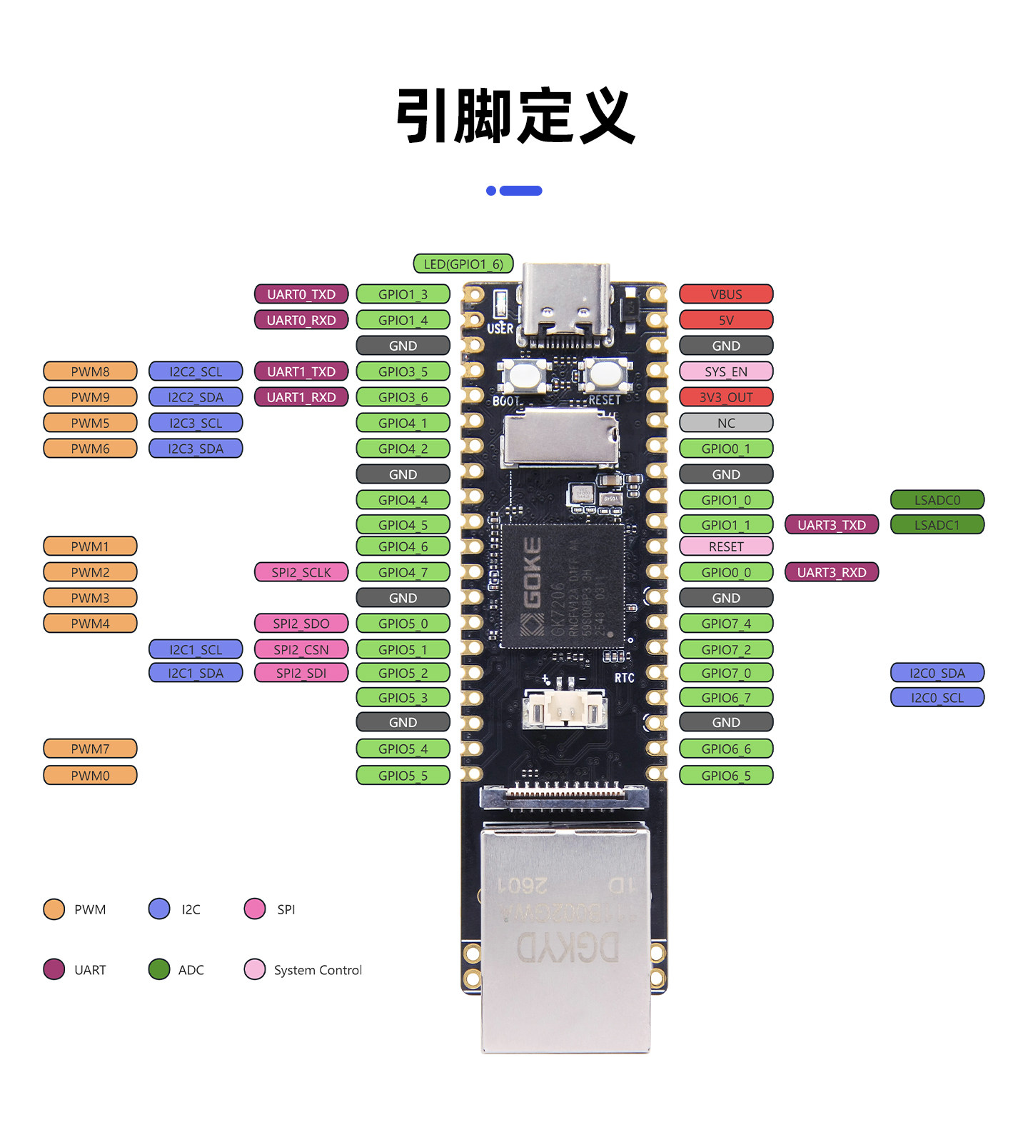
Pin layout

GPIO number calculation

Each GPIO group has 8 GPIO pins. The GPIO number equals GPIO group * 8 + offset within the group. For example, the GPIO number of GPIO4_2 is 4 * 8 + 2 = 34. When using the character-device driver, for GPIO1_4: chip_path corresponds to /dev/gpiochip1, and line_offset corresponds to 4.

2. Character GPIO

2.1 Terminology

  • libgpiod

    libgpiod is the standard library for accessing GPIOs (general-purpose input/output) from the Linux user space, and is the official user-space interface to the modern GPIO subsystem (gpiolib character device interface).

  • ioctl

    ioctl is a device-control system call interface. Beyond read/write, it interacts with device drivers through a command code (request) and a structured parameter (arg) to implement device configuration, status query, and special control functions.

Note

libgpiod is the official Linux GPIO user-space reference library. It wraps the GPIO character device ioctl interface and provides unified APIs for requesting, controlling, and receiving events on GPIO lines. Functionally, it is the user-space abstraction layer for GPIO, but it still relies on ioctl to talk to the kernel's gpiolib.

Also: users can bypass libgpiod entirely and implement their own GPIO abstraction layer directly on ioctl.

2.2 Using the GPIO ioctl Interface

2.2.1 Header File

linux/gpio.h

This header defines common structures and ioctls:

  • struct gpiohandle_request
  • struct gpiohandle_data
  • struct gpioevent_request

and these ioctl commands:

  • GPIO_GET_CHIPINFO_IOCTL
  • GPIO_GET_LINEINFO_IOCTL
  • GPIO_GET_LINEHANDLE_IOCTL
  • GPIO_GET_LINEEVENT_IOCTL
  • GPIOHANDLE_GET_LINE_VALUES_IOCTL
  • GPIOHANDLE_SET_LINE_VALUES_IOCTL

2.2.2 Related Structures

gpiohandle_request

Used to request a normal input/output GPIO line.

Key members:

  • lineoffsets[]: line numbers
  • flags: input or output
  • default_values[]: default output value
  • consumer_label: consumer name shown to the kernel
  • fd: returns the line handle on success

gpiohandle_data

Used to read and write line levels.

Key members:

  • values[]: value of each line

gpioevent_request

Used to request an interrupt event line.

Key members:

  • lineoffset: line number
  • handleflags: usually input
  • eventflags: rising edge / falling edge / both edges
  • fd: returns the event fd on success

2.3 Implementing a Breathing-LED Application

See Quick Start / Deploying Your First Application.

Create and write gpio_hal.c

#include "gpio_hal.h"

#include <errno.h>
#include <fcntl.h>
#include <stdio.h>
#include <string.h>
#include <sys/ioctl.h>
#include <unistd.h>

int gpio_handle_init(gpio_handle_t *gpio_handle)
{
	struct gpiohandle_request req;

	if (gpio_handle == NULL || gpio_handle->chip_path == NULL) {
		errno = EINVAL;
		return -1;
	}

	gpio_handle->chip_fd = -1;
	gpio_handle->line_fd = -1;

	gpio_handle->chip_fd = open(gpio_handle->chip_path, O_RDONLY);
	if (gpio_handle->chip_fd < 0) {
		perror("open gpiochip");
		return -1;
	}

	memset(&req, 0, sizeof(req));
	req.lineoffsets[0] = gpio_handle->line_offset;
	req.flags = gpio_handle->gpio_mode;
	req.default_values[0] = gpio_handle->default_value ? 1 : 0;
	req.lines = 1;

	if (gpio_handle->consumer_label[0] != '\0') {
		strncpy(req.consumer_label,
			gpio_handle->consumer_label,
			sizeof(req.consumer_label) - 1);
		req.consumer_label[sizeof(req.consumer_label) - 1] = '\0';
	} else {
		strncpy(req.consumer_label, "gpio-led", sizeof(req.consumer_label) - 1);
		req.consumer_label[sizeof(req.consumer_label) - 1] = '\0';
	}

	if (ioctl(gpio_handle->chip_fd, GPIO_GET_LINEHANDLE_IOCTL, &req) < 0) {
		perror("GPIO_GET_LINEHANDLE_IOCTL");
		close(gpio_handle->chip_fd);
		gpio_handle->chip_fd = -1;
		return -1;
	}

	gpio_handle->line_fd = req.fd;
	return 0;
}

int gpio_set_value(gpio_handle_t *gpio_handle, int value)
{
	struct gpiohandle_data data;

	if (gpio_handle == NULL || gpio_handle->line_fd < 0) {
		errno = EINVAL;
		return -1;
	}

	memset(&data, 0, sizeof(data));
	data.values[0] = value ? 1 : 0;

	if (ioctl(gpio_handle->line_fd, GPIOHANDLE_SET_LINE_VALUES_IOCTL, &data) < 0) {
		perror("GPIOHANDLE_SET_LINE_VALUES_IOCTL");
		return -1;
	}

	return 0;
}

void gpio_handle_close(gpio_handle_t *gpio_handle)
{
	if (gpio_handle == NULL)
		return;

	if (gpio_handle->line_fd >= 0) {
		close(gpio_handle->line_fd);
		gpio_handle->line_fd = -1;
	}

	if (gpio_handle->chip_fd >= 0) {
		close(gpio_handle->chip_fd);
		gpio_handle->chip_fd = -1;
	}
}

Create and write gpio_hal.h

#ifndef GPIO_HAL_H
#define GPIO_HAL_H

#ifdef __cplusplus
extern "C" {
#endif

#include <linux/gpio.h>

#define GPIO_CONSUMER_LABEL_LEN 32

typedef struct gpio_handle_t {
	int chip_fd;
	const char *chip_path;
	unsigned int line_offset;
	unsigned int gpio_mode;
	int default_value;
	int line_fd;
	char consumer_label[GPIO_CONSUMER_LABEL_LEN];
} gpio_handle_t;

int gpio_handle_init(gpio_handle_t *gpio_handle);
int gpio_set_value(gpio_handle_t *gpio_handle, int value);
void gpio_handle_close(gpio_handle_t *gpio_handle);

#ifdef __cplusplus
}
#endif

#endif

Create and write main.c

#include "gpio_hal.h"

#include <linux/gpio.h>
#include <stdio.h>
#include <string.h>
#include <unistd.h>

#define LED_CHIP_PATH "/dev/gpiochip1"
#define LED_LINE      6

int main(void)
{
	gpio_handle_t led_handle;

	memset(&led_handle, 0, sizeof(led_handle));
	led_handle.chip_path = LED_CHIP_PATH;
	led_handle.line_offset = LED_LINE;
	led_handle.gpio_mode = GPIOHANDLE_REQUEST_OUTPUT;
	led_handle.default_value = 0;
	snprintf(led_handle.consumer_label, sizeof(led_handle.consumer_label), "led-gpio");

	if (gpio_handle_init(&led_handle) < 0) {
		perror("gpio_handle_init");
		return 1;
	}

	printf("LED GPIO set high\n");
	if (gpio_set_value(&led_handle, 1) < 0) {
		gpio_handle_close(&led_handle);
		return 1;
	}

	sleep(5);

	printf("LED GPIO set low\n");
	if (gpio_set_value(&led_handle, 0) < 0) {
		gpio_handle_close(&led_handle);
		return 1;
	}

	gpio_handle_close(&led_handle);
	return 0;
}

Create and write the Makefile

SDK_DIR := $(shell cd $(shell pwd)/../../.. && /bin/pwd)

include $(SDK_DIR)/build/base.mk


TARGET := gpio

SRCS := main.c gpio_hal.c

OBJS := $(SRCS:.c=.o)

.PHONY: all clean install

all: $(TARGET)

$(TARGET): $(OBJS)
	$(CC) $(SDK_LD_CFLAGS) -o $@ $^

%.o: %.c
	$(CC) $(SDK_USR_CFLAGS) -c -o $@ $<

install: all
	@mkdir -p $(XMEDIA_ROOTFS_DIR)/usr/bin
	@cp -f $(TARGET) $(XMEDIA_ROOTFS_DIR)/usr/bin/$(TARGET)
	@chmod 755 $(XMEDIA_ROOTFS_DIR)/usr/bin/$(TARGET)
	@echo "Installed $(TARGET) to $(XMEDIA_ROOTFS_DIR)/usr/bin/$(TARGET)"

clean:
	rm -f $(TARGET) $(OBJS)

Build the application into the rootfs, log in to Pico-G1, and run the application

Expected result: The LED lights up for 5 seconds then turns off

Note

If the expected result is not achieved, the GPIO used by the LED may have been muxed to another function. Run the following commands:

xmmd.l 0x11980018 # View the value of the GPIO1_6 register
xmmm 0x11980018 0x00001000 # Modify the register value

After modifying, run the application again.

3 Controlling GPIO via sysfs

3.1 Export a GPIO to User Space

In the /sys/class/gpio directory on the board, each GPIO device has its own folder. These folder names are gpio plus the pin number, for example /sys/class/gpio/gpio14 represents pin number 14, which is GPIO1_6. Users can view them with the following command:

~ # echo 14 > /sys/class/gpio/export
~ # ls /sys/class/gpio/
export      gpiochip0   gpiochip24  gpiochip40  gpiochip56  gpiochip8
gpio14      gpiochip16  gpiochip32  gpiochip48  gpiochip64  unexport

Note

echo 14 > /sys/class/gpio exports GPIO14 to user space; after export, /sys/class/gpio/gpio14 is created. Use echo 14 > /sys/class/gpio/unexport to unexport it.

3.2 GPIO Control Directory

The control directory of an exported GPIO (that is, /sys/class/gpio/gpio14) usually contains the following files:

~ # ls /sys/class/gpio/gpio14/
active_low  direction   power       uevent
device      edge        subsystem   value

active_low

Used to set whether the GPIO level logic is inverted. Example:

echo 1 > /sys/class/gpio/gpio14/active_low # Inverts the level logic of GPIO14

direction

Used to set the GPIO direction, i.e. whether it is input or output. Example:

echo in > /sys/class/gpio/gpio14/direction	# Input
echo out > /sys/class/gpio/gpio14/direction	# Output

power

Power-management-related directory/files; usually not operated on directly.

uevent

Related to device events; usually not the most common file for daily manual GPIO control.

device

Indicates the device information that this GPIO belongs to.

edge

echo both > /sys/class/gpio/gpio14/edge

Configures the interrupt trigger edge. Common values:

  1. none: no interrupt
  2. rising: interrupt on rising edge
  3. falling: interrupt on falling edge
  4. both: interrupt on both edges

subsystem

Indicates which subsystem this GPIO belongs to.

value

Used to read or set the GPIO level value.

cat /sys/class/gpio/gpio14/value # Read the level
echo 1 > /sys/class/gpio/gpio14/value	# Set to high level
echo 0 > /sys/class/gpio/gpio14/value	# Set to low level
Edit this page on GitHub
Next
UART Serial Communication