
HOME
Shop
  • English
  • 简体中文
HOME
Shop
  • English
  • 简体中文
  • Product Series

    • FPGA+ARM

      • GM-3568JHF

        • Introduction

          • GM-3568JHF Introduction
        • Quick Start

          • Preface
          • Environment Setup
          • Compilation Notes
          • Flashing Guide
          • Debugging Tools
          • Software Update
          • Viewing System Information
          • Test Commands
          • Application Compilation
          • Source Code Access
        • Peripherals & Interfaces

          • USB
          • Display and Touch
          • Ethernet
          • WIFI
          • Bluetooth
          • TF-Card
          • Audio
          • Serial Port
          • CAN
          • RTC
        • Application Development

          • UART Read/Write Demo
          • Key Detection Demo
          • LED Blink Demo
          • MIPI Screen Detection Demo
          • Read USB Device Information Demo
          • FAN Detection Demo
          • FPGA FSPI Communication Demo
          • FPGA DMA Read/Write Demo
          • GPS Debugging Demo
          • Ethernet Test Demo
          • RS485 Read/Write Demo
          • FPGA I2C Read/Write Demo
          • PN532 NFC Card-Reading Demo
          • TF Card Read/Write Demo
        • QT Development

          • ARM64 Cross-Compiler Environment Setup
          • Adding a QT Program to Boot Auto-Start
        • RKNN_NPU Development

          • RK3568 NPU Overview
          • Development Environment Setup
          • Run the Official YOLOv5 Example
        • FPGA Development

          • ARM and FPGA Communication
          • FPGA Development Manual
        • Others

          • Modifying the Root Filesystem
          • System Auto-Start Services
        • Downloads

          • Downloads
      • MB-E30P

        • Introduction

          • MB-E30P Introduction
        • Quick Start

          • Preface
          • Environment Setup
          • Compilation Instructions
          • Flashing Guide
          • Debugging Tools
          • Software Update
          • Viewing Information
          • Test Commands
          • Application Compilation
          • Source Code Acquisition
        • Peripherals & Interfaces

          • USB
          • Display and Touch
          • Ethernet
          • WIFI
          • Bluetooth
          • TF-Card
          • Audio
          • RTC
        • Application Development

          • Key Detection Demo
          • LED Blink Demo
          • MIPI Screen Detection Demo
          • Read USB Device Information Demo
          • FAN Detection Demo
          • FPGA FSPI Communication Demo
          • FPGA DMA Read/Write Demo
          • Ethernet Test Demo
          • FPGA IIC Read/Write Demo
          • PN532 NFC Card Reading Demo
          • TF Card Read/Write Demo
        • QT Development

          • ARM64 Cross-Compiler Environment Setup
          • Adding a QT Program to the Boot Auto-Start Service
        • RKNN_NPU Development

          • RK3568 NPU Overview
          • Development Environment Setup
          • Run the Official YOLOv5 Example
          • Model Conversion In Detail
          • Run Custom Models on the Board
        • FPGA Development

          • ARM and FPGA Communication
          • FPGA Development Manual
        • Others

          • Modifying the Root Filesystem
          • System Auto-Start Service
        • Downloads

          • Downloads
    • ShimetaPi

      • M4-R1

        • Introduction

          • M4-R1 Introduction
        • Quick Start

          • OpenHarmony Overview
          • Image Burning
          • Application Development Quick Start
          • Device Development Quick Start
        • Application Development

          • ArkUI

            • ArkTS Language Overview
            • UI Components - Row Container Introduction
            • UI Components - Column Container Introduction
            • UI Components - Text Component
            • UI Components - Toggle Component
            • UI Components - Slider Component
            • UI Components - Animation Component & Transition Component
          • Documentation

            • OpenHarmony Official Materials
          • Development Notes

            • Full-SDK Replacement Tutorial
            • Introducing and Using Third-Party Libraries
            • HDC Debugging
            • Restore Factory Mode via Command Line
            • Upgrade App to System Permission
          • First App

            • Build Your First ArkTS Application - HelloWorld
          • Demos

            • Serial-Debug-Assistant Application Demo
            • Writing-Board Application Demo
            • Digital Clock Application Demo
            • Wi-Fi Information Acquisition Application Demo
        • Device Development

          • Ubuntu Development

            • Environment Setup
            • Download Source Code
            • Compile Source Code
          • DevEco Device Tool

            • Tool Introduction
            • Development Environment Construction
            • Import the SDK
            • HUAWEI DevEco Tool Function Introduction
        • Kernel Peripherals & Interfaces

          • Guide
          • Device Tree Introduction
          • NAPI Introduction
          • ArkTS Introduction
          • NAPI Development Hands-on Demo
          • GPIO Introduction
          • I2C Communication
          • SPI Communication
          • PWM Control
          • UART Communication
          • TF Card (MicroSD)
          • Screen (Display)
          • Touch
          • Ethernet
          • M.2 SSD
          • Audio
          • WIFI & BT
          • Camera
        • Downloads

          • Downloads
      • M5-R1

        • Introduction

          • M5-R1 Development Docs
        • Quick Start

          • Image Burning
          • Environment Setup
          • Download Source Code
        • Peripherals & Interfaces

          • Raspberry Pi Interfaces
          • GPIO Interface
          • I2C Interface
          • SPI Communication
          • PWM Control
          • Serial Port Communication
          • TF Card
          • Display
          • Touch
          • Audio
          • RTC
          • Ethernet
          • M.2
          • MINI-PCIE
          • Camera
          • WIFI & BT
        • Downloads

          • Downloads
      • Pico-G1

        • Product Overview

          • Product Introduction
          • SDK Version Information
        • Quick Start

          • Development Environment Setup
          • Image Build
          • Image Flashing
          • System Login
          • Network Configuration
          • File Transfer
          • SDK Directory Structure
          • Deploying Your First Application
          • Deploying Your First Driver
          • Mounting an SD Card
        • Peripherals & Interfaces

          • GPIO Control
          • UART Serial Communication
          • I2C Communication
          • SPI Communication
        • MPP Media Development

          • MPP Media Processing Software
          • Image Processing Chain
          • Video Input
          • Image Encoding
        • NPU & AI

          • NPU Driver and Runtime Library Architecture
          • .xmm Model Loading
          • SVP Video Processing
          • AI Noise Reduction (AI_NR)
        • Application Samples

          • Encryption/Decryption Application
          • ADC Acquisition Application
          • Low-Power Application
          • Audio Processing Application
          • Video Encoding Application
          • Video Input Application
          • Video Graphics Subsystem (VGS) Application
          • 08 Region Overlay Application
          • 09 Intelligent Video Engine Application
          • 10 UVC Webcam Application
          • 11 All-in-One Quickstart Application
          • 12 FPN Correction Application
          • 13 Regional Motion Detection Application
          • 14 MTCNN Face Detection Application
        • Expansion Board Peripheral Examples

          • 00 - Pico Expansion Board Peripheral Examples Overview
          • 01 - OLED Display Application
          • 02 - TFT Display Application
          • 03 - MPU6050 Gyroscope Application
          • 04 - ADC Acquisition Application
          • 05 - Passive Buzzer Application
          • 06 - MQ Gas Sensor Application
          • 07 - GPS Positioning Application
          • 08 - SHT20 Temperature & Humidity Application
          • 09 - Ultrasonic Ranging Application
          • 10 - SpO2 Sensor Application
          • 11 - DC Motor Control Application
          • 12 - Servo Control Application
    • OpenHarmony

      • SC-3568HA

        • Introduction

          • SC-3568HA Overview
        • Quick Start Guide

          • OpenHarmony Overview
          • Image Flashing
          • Setting Up the Development Environment
          • Hello World Application and Deployment
        • Application Development

          • ArkUI

            • Introduction to ArkTS Language
            • Introduction to UI Components and Practical Applications (Part 1)
            • Introduction to UI Components and Practical Applications (Part 2)
            • Introduction to UI Components and Practical Applications (Part 3)
          • Expand

            • Getting Started Guide
            • Referencing and Using Third-Party Libraries
            • Application Compilation and Deployment
            • Command-Line Factory Reset
            • System Debugging -- HDC Debugging
            • APP Stability Testing
            • Chapter 7 Application Testing
        • Device Development

          • Environment Setup
          • Download Source Code
          • Compiling Source Code
        • Peripheral And Interface

          • Raspberry Pi interface
          • GPIO Interface
          • I2C Interface
          • SPI communication
          • PWM (Pulse Width Modulation) control
          • Serial port communication
          • TF Card
          • Display Screen
          • Touch
          • Audio
          • RTC
          • Ethernet
          • M.2
          • MINI-PCIE
          • Camera
          • WIFI&BT
          • Raspberry Pi expansion board
        • Downloads

          • Downloads
      • M-K1HSE

        • Introduction

          • M-K1HSE Introduction
        • Quick Start

          • Development environment construction
          • Source code acquisition
          • Compilation Notes
          • Burning Guide
        • Application Development

          • Application Development Environment Setup
          • First Application - Hello World
        • Peripherals and interfaces

          • 01 Audio
          • 02 RS485
          • 03 Display
        • System customization development

          • System transplant
          • System customization
          • Driver Development
          • System Debugging
          • OTA Update
        • Downloads

          • Downloads
    • HVS Camera

      • Quick Start

        • SDK Overview
        • Downloads
        • Your First C++ Program
        • Python Data Analysis
        • MultiVision Studio
      • Development

        • Programming Guides

          • Open Camera
          • Read Events
          • Recording & Replay
          • Event Processing (Denoising)
          • Display & Visualization
          • Tuning
          • Capture APS Image
        • Toolkit SDK

          • Hybrid Vision Toolkit
          • Quick Start
          • C++ API
          • Python API
        • Algorithm

          • Hybrid Vision Algo
          • Hybrid Vision Algo API
          • Windows Algo SDK
        • Samples Overview
        • Applications
      • Fundamentals

        • Event Camera Fundamentals
        • HVS Hybrid Vision
        • Event Visualization
        • Data Formats Reference
        • Glossary
        • Bias & Tuning
        • Video Tutorials
      • USB Cameras

        • HVS Camera Quick Start
        • Networking Capabilities

          • HVS Camera System Architecture
          • EVS Network Server
          • EVS Time Sync
          • Web Window
        • HVS Camera Compatibility Matrix
        • FAQ & Troubleshooting Guide
        • Products

          • CF-NRS1 (Lingguang No.1 Hybrid Vision Camera)
      • MIPI Modules

        • MIPI Module Quick Start
        • Carrier Boards

          • RDK X5 Carrier Board Adaptation
          • Raspberry Pi Carrier Board Adaptation
          • Digua Pi Carrier Board Adaptation
          • ShimeTai Board Carrier Board Adaptation
        • MIPI Module Compatibility Matrix
        • Products

          • EVS_003 Sensor Module
    • AI-model

      • 1684XB-32T

        • Introduction

          • AIBOX-1684XB-32 Introduction
        • Quick Start

          • First Use
          • Network Configuration
          • Disk Usage
          • Memory Allocation
          • Fan Control Strategy
          • Firmware Upgrade
          • Cross Compilation
          • Model Quantization
        • Application Development

          • Development Overview

            • Sophgo SDK Development
            • Sophgo Demo Introduction
          • Large Language Models

            • Deploying Llama3 Example
            • Sophon LLM_api_server Development
            • Deploying MiniCPM-V-2_6
            • Qwen-2-5-VL Image and Video Recognition Demo
            • Qwen3-chat Demo
            • Qwen3-Qwen Agent-MCP Development
            • Qwen3-langchain-AI Agent
          • Deep Learning

            • ResNet (Image Classification)
            • LPRNet (License Plate Recognition)
            • SAM (General Image Segmentation Foundation Model)
            • YOLOv5 (Object Detection)
            • OpenPose (Human Keypoint Detection)
            • PP-OCR (Optical Character Recognition)
        • Downloads

          • Downloads
      • 1684X-416T

        • Introduction

          • AIBOX-1684X-416 Introduction
        • Demo Quick Guide

          • ShimeTai Intelligent Monitoring Demo Quick Usage Guide
      • RDK-X5

        • Introduction

          • RDK-X5 Hardware Introduction
        • Quick Start

          • RDK-X5 Quick Start
        • Application Development

          • AI Online Model Development

            • Experiment 01 - Access Volcengine Doubao AI
            • Experiment 02 - Image Analysis
            • Experiment 03 - Multimodal Visual Analysis & Localization
            • Experiment 04 - Multimodal Image-Text Comparison
            • Experiment 05 - Multimodal Document/Table Analysis
            • Experiment 06 - Camera-based AI Visual Analysis
          • Large Language Models

            • Experiment 01 - Speech Recognition
            • Experiment 02 - Voice Conversation
            • Experiment 03 - Multimodal Image Analysis - Voice
            • Experiment 04 - Multimodal Image Comparison - Voice
            • Experiment 05 - Multimodal Document Analysis - Voice
            • Experiment 06 - Multimodal Vision Application - Voice
          • ROS2 Basics

            • Experiment 01 - Environment Setup
            • Experiment 02 - Create & Build a Workspace Package
            • Experiment 03 - Run ROS2 Topic Communication Node
            • Experiment 04 - ROS2 Camera Application
          • 40-pin IO Development

            • Experiment 01 - GPIO Output (LED Blink)
            • Experiment 02 - GPIO Input
            • Experiment 03 - Button-controlled LED
            • Experiment 04 - PWM Output
            • Experiment 05 - Serial Output
            • Experiment 06 - I2C Experiment
            • Experiment 07 - SPI Experiment
          • USB Module Usage

            • Experiment 01 - USB Voice Module Usage
            • Experiment 02 - Sound Source Localization Module
          • Machine Vision Practice

            • Experiment 01 - Open USB Camera
            • Experiment 02 - Color Recognition
            • Experiment 03 - Gesture Recognition
            • Experiment 04 - YOLOv5 Object Detection
      • RDK-S100

        • Introduction

          • RDK-S100 Hardware Introduction
        • Quick Start

          • RDK-S100 Quick Start
        • Application Development

          • AI Online Model Development

            • Experiment 01 - Access Volcengine Doubao AI
            • Experiment 02 - Image Analysis
            • Experiment 03 - Multimodal Visual Analysis & Localization
            • Experiment 04 - Multimodal Image-Text Comparison
            • Experiment 05 - Multimodal Document/Table Analysis
            • Experiment 06 - Camera-based AI Visual Analysis
          • Large Language Models

            • Experiment 01 - Speech Recognition
            • Experiment 02 - Voice Conversation
            • Experiment 03 - Multimodal Image Analysis - Voice
            • Experiment 04 - Multimodal Image Comparison - Voice
            • Experiment 05 - Multimodal Document Analysis - Voice
            • Experiment 06 - Multimodal Vision Application - Voice
          • ROS2 Basics

            • Experiment 01 - Environment Setup
            • Experiment 02 - Create & Build a Workspace Package
            • Experiment 03 - Run ROS2 Topic Communication Node
            • Experiment 04 - ROS2 Camera Application
          • 40-pin IO Development

            • Experiment 01 - GPIO Output (LED Blink)
            • Experiment 02 - GPIO Input
            • Experiment 03 - Button-controlled LED
            • Experiment 04 - PWM Output
            • Experiment 05 - Serial Output
            • Experiment 06 - I2C Experiment
            • Experiment 07 - SPI Experiment
          • USB Module Usage

            • Experiment 01 - USB Voice Module Usage
            • Experiment 02 - Sound Source Localization Module
          • Machine Vision Practice

            • Experiment 01 - Open USB Camera
            • Experiment 02 - Image Processing Basics
            • Experiment 03 - Object Detection
            • Experiment 04 - Image Segmentation
      • RK1828

        • Introduction

          • M5-182X-A1 AI Edge Box - Product Introduction
          • M5-182X-A1 Hardware Specifications
          • M5-182X-A1 Usage & Safety
        • Quick Start

          • M5-182X-A1 Image Flashing
          • RK182X Hardware Installation & Verification
          • RK182X Development Environment Quick Setup
          • RK182X SDK Overview
          • RK182X Environment Setup in Detail
          • RK182X Quick Start
          • Vendor SDK Data Extraction Record
        • Development Guide

          • ClawChips Architecture and Principles
          • SKILL User Manual
          • RK182X Series LLM Inference (RK1828 Model)
          • RK182X Series CNN Inference (RK1828 Model)
          • Model Conversion
          • RK182X AI Agent Application Development Guide
          • RK182X Industrial Anomaly Detection Application
        • SDK Reference

          • RKNN3-SDK Overview

            • RKNN3 SDK Overview
          • RKNN3-Toolkit

            • RKNN3 Toolkit Installation and Usage
          • RKLLM

            • RKLLM On-Device LLM Inference
          • RK182X Series NPU Overview and Architecture (RK1828 Model)
          • RK182X INT8 Quantized Inference Deployment
          • RK182X MPP Multimedia Framework
          • MPP Details

            • RK182X Video Decoding
            • RK182X Video Encoding
          • NPU Details

            • RKNN Model Conversion
            • RK182X NPU INT8 Quantized Inference
            • RK182X Multi-Model Parallel Inference
          • RGA Details

            • RK182X RGA 2D Graphics Acceleration
          • VPU Details

            • RK182X VPU Codec
        • Hardware Reference

          • RK182X Series Hardware Architecture Overview (RK1828 Model)
          • RK182X Pin Definitions and Multiplexing Configuration
          • RK182X Pin Definitions
          • RK182X Power Management
          • RK182X Clock and PLL Configuration
          • RK182X Clock and Frequency Configuration
        • Tutorials

          • Hello World
          • Hello RK1828 - The First Program
          • RTSP Streaming
          • RTSP Streaming + AI Analysis
          • ShiMetaPi AI Lobster One-Click Deployment
          • PaddleOCR-VL Text Recognition
          • Qwen3-1.7B LLM Text Chat
          • AI Multi-View Inspection (Qwen3-VL Wrapper)
          • YOLOv5 Object Detection
        • Downloads

          • Downloads
        • FAQ

          • FAQ
    • Core-Board

      • C-3568BQ

        • Introduction

          • C-3568BQ Overview
      • C-3588LQ

        • Introduction

          • C-3588LQ Overview
      • GC-3568JBAF

        • Introduction

          • GC-3568JBAF Overview
      • C-K1BA

        • Introduction

          • C-K1BA Overview
    • Software Platform

      • ShiMetaPi Workbench

        • Introduction

          • Product Overview
          • Core Architecture
          • Feature Entries
          • Supported Hardware
          • Release Notes
        • Quick Start

          • Install & Login
          • Connect the Device
          • Set Up the Environment
          • Connect to AIHub
          • First Inference
        • User Guide

          • Workspace Overview
          • Device Manager
          • Model Market
          • One-Click Deploy
          • Vision — SVP
          • Vision - Custom Models
          • shimeta-py IDE
          • Terminal
          • Agent Debug Assistant
          • Settings and Resources
        • FAQ

          • Installation & Login
          • Device Connection
          • Models & Deployment
          • Vision & Runtime
          • Settings & Other
      • ShimetaPi Repository

        • Introduction

          • ShimetaPi Software Repository
        • Pico G1 (GK7206)

          • Quick Start

            • Installation & First Inference
            • shimeta_infer — Image Inference
            • shimeta_camera — Real-time Camera Inference
            • SVP Scene Detection
            • File Transfer & Built-in Model Reference
            • FAQ
          • HTTP API & Python SDK

            • HTTP API Reference
      • Model Fine-tuning Platform

        • Introduction

          • Model Training Platform
        • Quick Start

          • Register & Login
          • Create Your First Model (30-Minute Quick Experience)
        • Training Guide

          • Data Preparation & Annotation
          • Training Parameter Configuration
          • Start & Monitor Training
          • Model Evaluation & Testing
        • Model Deployment

          • Export Model
          • Deploy to Edge Device

01 - OLED Display Application

This chapter describes the OLED display application example on the Pico-G1 expansion board — oled_display. It demonstrates how to drive an SSD1306 OLED screen over the I2C interface to show a welcome screen and real-time system information. It is a classic example for learning I2C communication and display driver programming, covering the full technology stack from low-level I2C operations to high-level graphics drawing.

The application source code lives in the SDK directory source/app/01_oled_display/, providing a complete I2C character-device implementation and OLED driver — an important reference for learning display programming.

1 Application Overview

1.1 Features

  • I2C communication: demonstrates read/write operations through the Linux I2C character-device interface
  • OLED driver: complete SSD1306 driver implementation (initialization, drawing, refresh)
  • Graphics display: basic graphics functions such as text rendering, pixel drawing, and screen clearing
  • Real-time info: displays uptime, CPU load, memory usage, and other live system information
  • Font support: built-in 8×16 ASCII bitmap font (0x20~0x7E)
  • Multilingual support: the font-generation tool can build custom glyph libraries

1.2 Technical Specifications

ParameterValue
OLED modelSSD1306, 128×64 pixels
Communication interfaceI2C (I2C3, /dev/i2c-3)
Slave address0x3C (SA0 grounded; 0x3D when pulled high)
I2C speed100kHz (standard mode)
Display buffer128×64 monochrome bitmap (1KB framebuffer)
Font size8×16 pixel ASCII font
Refresh interval1 second (configurable)

1.3 Test Case List

indexNameTest commandExpected result (success)Possible causes of failure
1Welcome screen./oled_display or ./oled_display --onceShows the "ShimetaPi Pico-G1" welcome screen, then system info after 3 secondsI2C connection failure, wrong OLED address
2Continuous refresh./oled_display (no arguments)After the welcome screen, system info refreshes every second (uptime/loadavg/memory)Same as above
3Argument test./oled_display -hShows help information—

1.4 Directory Structure

source/app/01_oled_display/
├── Makefile              # Build script
├── main.c                # Main program
├── i2c_hal.c              # I2C HAL layer implementation
├── i2c_hal.h              # I2C HAL layer header
├── ssd1306.c              # SSD1306 driver implementation
├── ssd1306.h              # SSD1306 driver header
├── font8x16.h             # 8×16 ASCII bitmap font
├── gen_font8x16.py        # Font generation tool (Python)
└── README.md              # Documentation

2 Hardware Connection

2.1 Pin Definition

SignalOn-board GPIOControllerDevice node
SCLGPIO4_1I2C3/dev/i2c-3
SDAGPIO4_2I2C3/dev/i2c-3
VCC3.3V——
GNDGND——

2.2 Hardware Circuit

Standard I2C bus wiring (pull-up resistors are usually integrated on the OLED module):

     Pico-G1                    SSD1306 OLED
  ┌───────────┐              ┌──────────────┐
  │           │              │              │
  │ GPIO4_1 ──┼────── SCL ──┤ SCL          │
  │           │      │       │              │
  │ GPIO4_2 ──┼────── SDA ──┤ SDA          │
  │           │      │       │              │
  │    3.3V ──┼─────────────┤ VCC          │
  │           │              │              │
  │     GND ──┼─────────────┤ GND          │
  │           │              │   SA0 ─── GND│ (address 0x3C)
  └───────────┘              └──────────────┘

Address selection jumper

  • SA0 tied to GND: I2C address = 0x3C (default)
  • SA0 tied to VCC: I2C address = 0x3D
  • Some modules have no SA0 pin and are fixed at 0x3C

2.3 Pin Multiplexing

The GPIO4_1/GPIO4_2 pin pair is physically multiplexed as I2C3:

  • Register address: iocfg_ctrl2 @ 0x112C0000
  • Default function: I2C3 (configured by the BootROM/bootloader)
  • Kernel status: the i2c_bus3 node has status="ok"
  • Device node: /dev/i2c-3 is created automatically by the kernel

Pin-mux conclusion

This SoC has no standard pinctrl driver; pin functions are controlled by the IOCFG registers. GPIO4_1/GPIO4_2 are already in their I2C3 function out of reset via the SoC reset defaults / BootROM, so no manual configuration is needed.

3 Build and Deployment

3.1 Prerequisites

Before building this application, make sure the following preparations are complete:

  1. SDK environment ready: set up the cross-compilation toolchain and SDK by following Development Environment Setup
  2. Kernel configuration confirmed: make sure the kernel has CONFIG_I2C_CHARDEV=y and CONFIG_I2C_LOTUS=y enabled
  3. Hardware connected: the OLED module is correctly wired to GPIO4_1/GPIO4_2

3.2 Building the Application

# Set the toolchain path
export PATH=$PATH:<SDK>/tools/linux/toolchains/arm-gcc12.2.0-linux-uclibceabi/bin

# Enter the example directory
cd <SDK>/source/app/01_oled_display

# Build
make

# Clean
make clean

After a successful build, the executable oled_display is generated in the current directory.

3.3 Deploying to the Board

# Transfer to the development board with SCP
scp oled_display root@<board-IP>:/usr/bin/

# Or download via TFTP
tftp -g -r oled_display <board-IP>

3.4 Running the Application

# Add execute permission
chmod +x /usr/bin/oled_display

# Run the OLED display example
/usr/bin/oled_display              # Welcome screen, then system info refreshed every second
/usr/bin/oled_display --once       # Welcome screen only, exits after 3 seconds
/usr/bin/oled_display -h           # Show help information

Once started, the OLED screen shows the ShimetaPi welcome screen; after 3 seconds it starts displaying real-time system information. Press Ctrl+C to exit.

3.5 Expected Output

Console output

/mnt # ./oled_display
[oled] init SSD1306 @ /dev/i2c-3 addr 0x3c ...
[oled] pad 0x100C0010 -> 0x00001002
[oled] pad 0x100C0014 -> 0x00001002
[oled] 初始化成功,开始显示。

OLED screen display
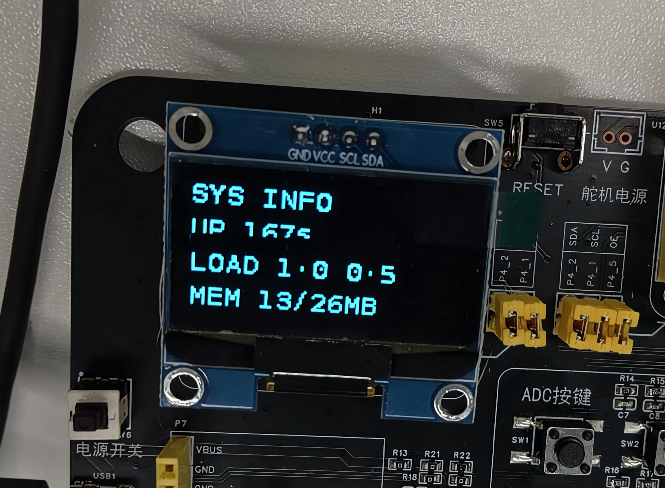
OLED display effect

Fixed and variable parts

  • Fixed part: the display format and layout (matches the fixed code)
  • Variable part: the system information values (updated on every refresh)

4 Internal Execution Logic

4.1 Application Architecture

This application uses a layered design consisting of a hardware abstraction layer, a driver layer, and an application layer:

// Application layer (main.c)
int main(int argc, char *argv[])
{
    // 1. Initialize the I2C HAL layer
    i2c_init(OLED_I2C_BUS, OLED_I2C_ADDR);

    // 2. Initialize the OLED driver
    ssd1306_init();

    // 3. Show the welcome screen
    ssd1306_display_welcome();
    sleep(3);

    // 4. Main loop refreshing system information
    while (1) {
        ssd1306_clear();
        ssd1306_display_system_info();
        ssd1306_refresh();
        sleep(1);
    }

    return 0;
}

4.2 I2C HAL Layer Implementation

The I2C HAL layer wraps the Linux I2C character-device operations:

// I2C initialization
int i2c_init(int bus, int addr)
{
    char dev_path[32];
    snprintf(dev_path, sizeof(dev_path), "/dev/i2c-%d", bus);

    int fd = open(dev_path, O_RDWR);
    if (fd < 0) {
        perror("打开 I2C 设备失败");
        return -1;
    }

    // Set the slave address
    if (ioctl(fd, I2C_SLAVE, addr) < 0) {
        perror("设置 I2C 地址失败");
        close(fd);
        return -1;
    }

    return fd;
}

// I2C write
int i2c_write(uint8_t *data, uint16_t len)
{
    return write(i2c_fd, data, len);
}

// I2C read
int i2c_read(uint8_t *data, uint16_t len)
{
    return read(i2c_fd, data, len);
}

4.3 SSD1306 Driver Implementation

The SSD1306 driver implements full OLED control:

// OLED initialization sequence
void ssd1306_init(void)
{
    // Turn the display off
    ssd1306_command(SSD1306_DISPLAY_OFF);

    // Set clock divider and frequency
    ssd1306_command(SSD1306_SET_CLOCK_DIV);
    ssd1306_command(0x80);

    // Set the multiplex ratio
    ssd1306_command(SSD1306_SET_MUX_RATIO);
    ssd1306_command(0x3F);  // 64MUX

    // Set the display offset
    ssd1306_command(SSD1306_SET_DISPLAY_OFFSET);
    ssd1306_command(0x00);

    // Set the start line
    ssd1306_command(SSD1306_SET_START_LINE | 0x0);

    // Enable the charge pump
    ssd1306_command(SSD1306_CHARGE_PUMP);
    ssd1306_command(0x14);  // 0x10 disable, 0x14 enable

    // Set the memory addressing mode
    ssd1306_command(SSD1306_MEMORY_ADDR_MODE);
    ssd1306_command(0x00);  // horizontal addressing mode

    // Set the column address range
    ssd1306_command(SSD1306_SET_COLUMN_ADDR);
    ssd1306_command(0x00);  // start column
    ssd1306_command(0x7F);  // end column (127)

    // Set the page address range
    ssd1306_command(SSD1306_SET_PAGE_ADDR);
    ssd1306_command(0x00);  // start page
    ssd1306_command(0x07);  // end page (7)

    // Configure segment remap and COM scan direction
    ssd1306_command(SSD1306_SET_SEGMENT_REMAP | 0x1);
    ssd1306_command(SSD1306_SET_COM_SCAN_DEC);

    // Set the COM pins configuration
    ssd1306_command(SSD1306_SET_COM_PINS);
    ssd1306_command(0x12);

    // Set the contrast
    ssd1306_command(SSD1306_SET_CONTRAST);
    ssd1306_command(0xCF);

    // Set the pre-charge period
    ssd1306_command(SSD1306_SET_PRECHARGE);
    ssd1306_command(0xF1);

    // Set the VCOMH deselect level
    ssd1306_command(SSD1306_SET_VCOMH);
    ssd1306_command(0x40);

    // Turn the display on
    ssd1306_command(SSD1306_DISPLAY_ON);
}

// Send a command
void ssd1306_command(uint8_t cmd)
{
    uint8_t buf[2] = {0x00, cmd};  // Co=0, D/C#=0 means command
    i2c_write(buf, 2);
}

// Send data
void ssd1306_data(uint8_t *data, uint16_t len)
{
    uint8_t buf[len + 1];
    buf[0] = 0x40;  // Co=0, D/C#=1 means data
    memcpy(&buf[1], data, len);
    i2c_write(buf, len + 1);
}

4.4 Drawing Functions

The driver layer provides basic drawing functions:

// Set a pixel
void ssd1306_set_pixel(int x, int y, int color)
{
    if (x < 0 || x >= OLED_WIDTH || y < 0 || y >= OLED_HEIGHT)
        return;

    if (color)
        buffer[x + (y / 8) * OLED_WIDTH] |= (1 << (y % 8));
    else
        buffer[x + (y / 8) * OLED_WIDTH] &= ~(1 << (y % 8));
}

// Clear the screen
void ssd1306_clear(void)
{
    memset(buffer, 0, sizeof(buffer));
}

// Refresh the display
void ssd1306_refresh(void)
{
    // Set the column address
    ssd1306_command(SSD1306_SET_COLUMN_ADDR);
    ssd1306_command(0x00);
    ssd1306_command(0x7F);

    // Set the page address
    ssd1306_command(SSD1306_SET_PAGE_ADDR);
    ssd1306_command(0x00);
    ssd1306_command(0x07);

    // Send the framebuffer data
    ssd1306_data(buffer, sizeof(buffer));
}

4.5 Fonts and Text Display

The built-in 8×16 ASCII bitmap font:

// Display a character
void ssd1306_putchar(int x, int y, char ch)
{
    if (ch < 0x20 || ch > 0x7E)
        ch = ' ';  // replace non-printable characters with a space

    const uint8_t *font = &font8x16[(ch - 0x20) * 16];

    for (int row = 0; row < 16; row++) {
        uint8_t line = font[row];
        for (int col = 0; col < 8; col++) {
            if (line & (0x80 >> col))
                ssd1306_set_pixel(x + col, y + row, 1);
        }
    }
}

// Display a string
void ssd1306_puts(int x, int y, const char *str)
{
    int orig_x = x;
    while (*str) {
        if (*str == '\n') {
            x = orig_x;
            y += 16;
        } else {
            ssd1306_putchar(x, y, *str);
            x += 8;
            if (x >= OLED_WIDTH) {
                x = orig_x;
                y += 16;
            }
        }
        str++;
    }
}

5 Key Programming Points

5.1 I2C Character-Device Operations

I2C write timing:

// SSD1306 I2C write format
uint8_t buf[2] = {control_byte, data_byte};

// Control byte format
// bit7 = Co (Continuation): 0 = last byte, 1 = more bytes follow
// bit6 = D/C# (Data/Command): 0 = command, 1 = data

// Write a command
buf[0] = 0x00;  // Co=0, D/C#=0
buf[1] = command_code;
i2c_write(buf, 2);

// Write data
buf[0] = 0x40;  // Co=0, D/C#=1
buf[1] = data_byte;
i2c_write(buf, 2);

5.2 Framebuffer Management

The SSD1306 uses the page addressing mode:

128×64 monochrome OLED memory layout:
- 8 pages (Page 0~7), each page covering 8 pixel rows
- 128 columns per page, 1 byte per column (8 bits map vertically to 8 pixels)
- Total framebuffer: 128 × 8 = 1024 bytes = 1KB

5.3 Font Format

The 8×16 bitmap font format:

// Each character takes 16 bytes (16 rows; each row of 8 pixels is stored in 1 byte)
const uint8_t font8x16[] = {
    // Character ' ' (0x20)
    0x00, 0x00, 0x00, 0x00, 0x00, 0x00, 0x00, 0x00,
    0x00, 0x00, 0x00, 0x00, 0x00, 0x00, 0x00, 0x00,

    // Character '!' (0x21)
    0x00, 0x00, 0x18, 0x3C, 0x3C, 0x3C, 0x18, 0x18,
    0x18, 0x00, 0x18, 0x18, 0x00, 0x00, 0x00, 0x00,

    // ... other characters
};

5.4 Error Handling

Every I2C operation should check its return value:

int ret = i2c_write(buf, len);
if (ret < 0) {
    perror("I2C 写入失败");
    // Try re-initializing I2C
    i2c_cleanup();
    i2c_init(OLED_I2C_BUS, OLED_I2C_ADDR);
}

6 Code Customization

6.1 Changing the I2C Bus or Address

Edit the macros at the top of ssd1306.h:

#define OLED_I2C_BUS   3      // I2C bus number (maps to /dev/i2c-3)
#define OLED_I2C_ADDR  0x3C   // I2C slave address (0x3C or 0x3D)

6.2 Changing the Resolution

Other resolutions (e.g. 128×32) are supported:

// Modify ssd1306.h
#define OLED_WIDTH   128
#define OLED_HEIGHT  32     // change to 32

// Adjust the corresponding parameters in the initialization sequence
ssd1306_command(SSD1306_SET_MUX_RATIO);
ssd1306_command(0x1F);      // 32MUX (changed to 0x1F)

ssd1306_command(SSD1306_SET_COM_PINS);
ssd1306_command(0x02);      // 128×32 configuration

ssd1306_command(SSD1306_SET_PAGE_ADDR);
ssd1306_command(0x00);
ssd1306_command(0x03);      // 4 pages (changed to 0x03)

6.3 Custom Fonts

Use gen_font8x16.py to generate a custom font:

# Run on the development machine (requires PIL/Pillow)
python3 gen_font8x16.py

The generated font8x16.h contains the full ASCII font (0x20~0x7E).

6.4 Adding Chinese Support

Extend the font library to support Chinese text:

// 16×16 Chinese character bitmaps
const uint8_t font16x16[][32] = {
    // Character "你"
    {0x00,0x00,0x00,0x00,0x7F,0xFE,0x40,0x02,0x40,0x02,0x7F,0xFC,...},
    // Character "好"
    {0x00,0x40,0x00,0x20,0x00,0x1F,0xFF,0xF0,0x00,0x10,0x00,0x10,...},
    // ... more characters
};

void ssd1306_putchar_chinese(int x, int y, uint16_t index)
{
    const uint8_t *font = font16x16[index];
    for (int row = 0; row < 16; row++) {
        uint16_t line = (font[row*2] << 8) | font[row*2+1];
        for (int col = 0; col < 16; col++) {
            if (line & (0x8000 >> col))
                ssd1306_set_pixel(x + col, y + row, 1);
        }
    }
}

7 Troubleshooting

ProblemPossible causeSolution
OLED stays darkI2C connection failure, wrong address, init failureCheck wiring, confirm the address, verify I2C communication
Garbled or corrupted screenWrong initialization sequence, wrong framebuffer formatCheck init parameters, confirm the framebuffer layout
Black screen with backlightContrast set too low, display not turned onAdjust contrast, confirm the DISPLAY_ON command
Partial display anomaliesWrong page address, wrong column address rangeCheck the addressing mode configuration
I2C communication timeoutBus speed mismatch, missing pull-up resistorsLower the I2C speed, add pull-up resistors
Some characters missingIncomplete font, wrong character rangeCheck font integrity, verify the character encoding

8 Advanced Extensions

8.1 Graphics Drawing

Add more graphics functions:

// Draw a horizontal line
void ssd1306_draw_hline(int x1, int x2, int y, int color)
{
    for (int x = x1; x <= x2; x++)
        ssd1306_set_pixel(x, y, color);
}

// Draw a vertical line
void ssd1306_draw_vline(int x, int y1, int y2, int color)
{
    for (int y = y1; y <= y2; y++)
        ssd1306_set_pixel(x, y, color);
}

// Draw a rectangle
void ssd1306_draw_rect(int x1, int y1, int x2, int y2, int color)
{
    ssd1306_draw_hline(x1, x2, y1, color);
    ssd1306_draw_hline(x1, x2, y2, color);
    ssd1306_draw_vline(x1, y1, y2, color);
    ssd1306_draw_vline(x2, y1, y2, color);
}

// Draw a filled rectangle
void ssd1306_fill_rect(int x1, int y1, int x2, int y2, int color)
{
    for (int y = y1; y <= y2; y++)
        for (int x = x1; x <= x2; x++)
            ssd1306_set_pixel(x, y, color);
}

8.2 Scrolling Display

Implement a text scrolling effect:

void ssd1306_scroll_text(const char *text, int line, int delay_ms)
{
    char buffer[32];
    int len = strlen(text);

    for (int offset = 0; offset < len; offset++) {
        ssd1306_clear();
        for (int i = 0; i < 16 && (offset + i) < len; i++) {
            buffer[i] = text[offset + i];
        }
        buffer[16] = '\0';
        ssd1306_puts(0, line, buffer);
        ssd1306_refresh();
        usleep(delay_ms * 1000);
    }
}

8.3 Image Display

Support bitmap-format images:

// Display an XBM image
void ssd1306_draw_xbm(int x, int y, int width, int height, const uint8_t *xbm)
{
    for (int row = 0; row < height; row++) {
        for (int col = 0; col < width; col++) {
            int byte_idx = (row * ((width + 7) / 8) + (col / 8));
            int bit_idx = col % 8;
            int pixel = (xbm[byte_idx] >> bit_idx) & 0x01;
            ssd1306_set_pixel(x + col, y + row, pixel);
        }
    }
}

// Usage example
const uint8_t logo_xbm[] = {
    // XBM data of a 16×16 icon
};
ssd1306_draw_xbm(56, 24, 16, 16, logo_xbm);

9 References

  • I2C Interface in Detail
  • TFT Display Application
  • MPU6050 Gyroscope Application
  • Development Environment Setup
  • SSD1306 datasheet
Edit this page on GitHub
Prev
00 - Pico Expansion Board Peripheral Examples Overview
Next
02 - TFT Display Application