
HOME
Shop
  • English
  • 简体中文
HOME
Shop
  • English
  • 简体中文
  • Product Series

    • FPGA+ARM

      • GM-3568JHF

        • Introduction

          • GM-3568JHF Introduction
        • Quick Start

          • Preface
          • Environment Setup
          • Compilation Notes
          • Flashing Guide
          • Debugging Tools
          • Software Update
          • Viewing System Information
          • Test Commands
          • Application Compilation
          • Source Code Access
        • Peripherals & Interfaces

          • USB
          • Display and Touch
          • Ethernet
          • WIFI
          • Bluetooth
          • TF-Card
          • Audio
          • Serial Port
          • CAN
          • RTC
        • Application Development

          • UART Read/Write Demo
          • Key Detection Demo
          • LED Blink Demo
          • MIPI Screen Detection Demo
          • Read USB Device Information Demo
          • FAN Detection Demo
          • FPGA FSPI Communication Demo
          • FPGA DMA Read/Write Demo
          • GPS Debugging Demo
          • Ethernet Test Demo
          • RS485 Read/Write Demo
          • FPGA I2C Read/Write Demo
          • PN532 NFC Card-Reading Demo
          • TF Card Read/Write Demo
        • QT Development

          • ARM64 Cross-Compiler Environment Setup
          • Adding a QT Program to Boot Auto-Start
        • RKNN_NPU Development

          • RK3568 NPU Overview
          • Development Environment Setup
          • Run the Official YOLOv5 Example
        • FPGA Development

          • ARM and FPGA Communication
          • FPGA Development Manual
        • Others

          • Modifying the Root Filesystem
          • System Auto-Start Services
        • Downloads

          • Downloads
      • MB-E30P

        • Introduction

          • MB-E30P Introduction
        • Quick Start

          • Preface
          • Environment Setup
          • Compilation Instructions
          • Flashing Guide
          • Debugging Tools
          • Software Update
          • Viewing Information
          • Test Commands
          • Application Compilation
          • Source Code Acquisition
        • Peripherals & Interfaces

          • USB
          • Display and Touch
          • Ethernet
          • WIFI
          • Bluetooth
          • TF-Card
          • Audio
          • RTC
        • Application Development

          • Key Detection Demo
          • LED Blink Demo
          • MIPI Screen Detection Demo
          • Read USB Device Information Demo
          • FAN Detection Demo
          • FPGA FSPI Communication Demo
          • FPGA DMA Read/Write Demo
          • Ethernet Test Demo
          • FPGA IIC Read/Write Demo
          • PN532 NFC Card Reading Demo
          • TF Card Read/Write Demo
        • QT Development

          • ARM64 Cross-Compiler Environment Setup
          • Adding a QT Program to the Boot Auto-Start Service
        • RKNN_NPU Development

          • RK3568 NPU Overview
          • Development Environment Setup
          • Run the Official YOLOv5 Example
          • Model Conversion In Detail
          • Run Custom Models on the Board
        • FPGA Development

          • ARM and FPGA Communication
          • FPGA Development Manual
        • Others

          • Modifying the Root Filesystem
          • System Auto-Start Service
        • Downloads

          • Downloads
    • ShimetaPi

      • M4-R1

        • Introduction

          • M4-R1 Introduction
        • Quick Start

          • OpenHarmony Overview
          • Image Burning
          • Application Development Quick Start
          • Device Development Quick Start
        • Application Development

          • ArkUI

            • ArkTS Language Overview
            • UI Components - Row Container Introduction
            • UI Components - Column Container Introduction
            • UI Components - Text Component
            • UI Components - Toggle Component
            • UI Components - Slider Component
            • UI Components - Animation Component & Transition Component
          • Documentation

            • OpenHarmony Official Materials
          • Development Notes

            • Full-SDK Replacement Tutorial
            • Introducing and Using Third-Party Libraries
            • HDC Debugging
            • Restore Factory Mode via Command Line
            • Upgrade App to System Permission
          • First App

            • Build Your First ArkTS Application - HelloWorld
          • Demos

            • Serial-Debug-Assistant Application Demo
            • Writing-Board Application Demo
            • Digital Clock Application Demo
            • Wi-Fi Information Acquisition Application Demo
        • Device Development

          • Ubuntu Development

            • Environment Setup
            • Download Source Code
            • Compile Source Code
          • DevEco Device Tool

            • Tool Introduction
            • Development Environment Construction
            • Import the SDK
            • HUAWEI DevEco Tool Function Introduction
        • Kernel Peripherals & Interfaces

          • Guide
          • Device Tree Introduction
          • NAPI Introduction
          • ArkTS Introduction
          • NAPI Development Hands-on Demo
          • GPIO Introduction
          • I2C Communication
          • SPI Communication
          • PWM Control
          • UART Communication
          • TF Card (MicroSD)
          • Screen (Display)
          • Touch
          • Ethernet
          • M.2 SSD
          • Audio
          • WIFI & BT
          • Camera
        • Downloads

          • Downloads
      • M5-R1

        • Introduction

          • M5-R1 Development Docs
        • Quick Start

          • Image Burning
          • Environment Setup
          • Download Source Code
        • Peripherals & Interfaces

          • Raspberry Pi Interfaces
          • GPIO Interface
          • I2C Interface
          • SPI Communication
          • PWM Control
          • Serial Port Communication
          • TF Card
          • Display
          • Touch
          • Audio
          • RTC
          • Ethernet
          • M.2
          • MINI-PCIE
          • Camera
          • WIFI & BT
        • Downloads

          • Downloads
      • Pico-G1

        • Product Overview

          • Product Introduction
          • SDK Version Information
        • Quick Start

          • Development Environment Setup
          • Image Build
          • Image Flashing
          • System Login
          • Network Configuration
          • File Transfer
          • SDK Directory Structure
          • Deploying Your First Application
          • Deploying Your First Driver
          • Mounting an SD Card
        • Peripherals & Interfaces

          • GPIO Control
          • UART Serial Communication
          • I2C Communication
          • SPI Communication
        • MPP Media Development

          • MPP Media Processing Software
          • Image Processing Chain
          • Video Input
          • Image Encoding
        • NPU & AI

          • NPU Driver and Runtime Library Architecture
          • .xmm Model Loading
          • SVP Video Processing
          • AI Noise Reduction (AI_NR)
        • Application Samples

          • Encryption/Decryption Application
          • ADC Acquisition Application
          • Low-Power Application
          • Audio Processing Application
          • Video Encoding Application
          • Video Input Application
          • Video Graphics Subsystem (VGS) Application
          • 08 Region Overlay Application
          • 09 Intelligent Video Engine Application
          • 10 UVC Webcam Application
          • 11 All-in-One Quickstart Application
          • 12 FPN Correction Application
          • 13 Regional Motion Detection Application
          • 14 MTCNN Face Detection Application
        • Expansion Board Peripheral Examples

          • 00 - Pico Expansion Board Peripheral Examples Overview
          • 01 - OLED Display Application
          • 02 - TFT Display Application
          • 03 - MPU6050 Gyroscope Application
          • 04 - ADC Acquisition Application
          • 05 - Passive Buzzer Application
          • 06 - MQ Gas Sensor Application
          • 07 - GPS Positioning Application
          • 08 - SHT20 Temperature & Humidity Application
          • 09 - Ultrasonic Ranging Application
          • 10 - SpO2 Sensor Application
          • 11 - DC Motor Control Application
          • 12 - Servo Control Application
    • OpenHarmony

      • SC-3568HA

        • Introduction

          • SC-3568HA Overview
        • Quick Start Guide

          • OpenHarmony Overview
          • Image Flashing
          • Setting Up the Development Environment
          • Hello World Application and Deployment
        • Application Development

          • ArkUI

            • Introduction to ArkTS Language
            • Introduction to UI Components and Practical Applications (Part 1)
            • Introduction to UI Components and Practical Applications (Part 2)
            • Introduction to UI Components and Practical Applications (Part 3)
          • Expand

            • Getting Started Guide
            • Referencing and Using Third-Party Libraries
            • Application Compilation and Deployment
            • Command-Line Factory Reset
            • System Debugging -- HDC Debugging
            • APP Stability Testing
            • Chapter 7 Application Testing
        • Device Development

          • Environment Setup
          • Download Source Code
          • Compiling Source Code
        • Peripheral And Interface

          • Raspberry Pi interface
          • GPIO Interface
          • I2C Interface
          • SPI communication
          • PWM (Pulse Width Modulation) control
          • Serial port communication
          • TF Card
          • Display Screen
          • Touch
          • Audio
          • RTC
          • Ethernet
          • M.2
          • MINI-PCIE
          • Camera
          • WIFI&BT
          • Raspberry Pi expansion board
        • Downloads

          • Downloads
      • M-K1HSE

        • Introduction

          • M-K1HSE Introduction
        • Quick Start

          • Development environment construction
          • Source code acquisition
          • Compilation Notes
          • Burning Guide
        • Application Development

          • Application Development Environment Setup
          • First Application - Hello World
        • Peripherals and interfaces

          • 01 Audio
          • 02 RS485
          • 03 Display
        • System customization development

          • System transplant
          • System customization
          • Driver Development
          • System Debugging
          • OTA Update
        • Downloads

          • Downloads
    • HVS Camera

      • Quick Start

        • SDK Overview
        • Downloads
        • Your First C++ Program
        • Python Data Analysis
        • MultiVision Studio
      • Development

        • Programming Guides

          • Open Camera
          • Read Events
          • Recording & Replay
          • Event Processing (Denoising)
          • Display & Visualization
          • Tuning
          • Capture APS Image
        • Toolkit SDK

          • Hybrid Vision Toolkit
          • Quick Start
          • C++ API
          • Python API
        • Algorithm

          • Hybrid Vision Algo
          • Hybrid Vision Algo API
          • Windows Algo SDK
        • Samples Overview
        • Applications
      • Fundamentals

        • Event Camera Fundamentals
        • HVS Hybrid Vision
        • Event Visualization
        • Data Formats Reference
        • Glossary
        • Bias & Tuning
        • Video Tutorials
      • USB Cameras

        • HVS Camera Quick Start
        • Networking Capabilities

          • HVS Camera System Architecture
          • EVS Network Server
          • EVS Time Sync
          • Web Window
        • HVS Camera Compatibility Matrix
        • FAQ & Troubleshooting Guide
        • Products

          • CF-NRS1 (Lingguang No.1 Hybrid Vision Camera)
      • MIPI Modules

        • MIPI Module Quick Start
        • Carrier Boards

          • RDK X5 Carrier Board Adaptation
          • Raspberry Pi Carrier Board Adaptation
          • Digua Pi Carrier Board Adaptation
          • ShimeTai Board Carrier Board Adaptation
        • MIPI Module Compatibility Matrix
        • Products

          • EVS_003 Sensor Module
    • AI-model

      • 1684XB-32T

        • Introduction

          • AIBOX-1684XB-32 Introduction
        • Quick Start

          • First Use
          • Network Configuration
          • Disk Usage
          • Memory Allocation
          • Fan Control Strategy
          • Firmware Upgrade
          • Cross Compilation
          • Model Quantization
        • Application Development

          • Development Overview

            • Sophgo SDK Development
            • Sophgo Demo Introduction
          • Large Language Models

            • Deploying Llama3 Example
            • Sophon LLM_api_server Development
            • Deploying MiniCPM-V-2_6
            • Qwen-2-5-VL Image and Video Recognition Demo
            • Qwen3-chat Demo
            • Qwen3-Qwen Agent-MCP Development
            • Qwen3-langchain-AI Agent
          • Deep Learning

            • ResNet (Image Classification)
            • LPRNet (License Plate Recognition)
            • SAM (General Image Segmentation Foundation Model)
            • YOLOv5 (Object Detection)
            • OpenPose (Human Keypoint Detection)
            • PP-OCR (Optical Character Recognition)
        • Downloads

          • Downloads
      • 1684X-416T

        • Introduction

          • AIBOX-1684X-416 Introduction
        • Demo Quick Guide

          • ShimeTai Intelligent Monitoring Demo Quick Usage Guide
      • RDK-X5

        • Introduction

          • RDK-X5 Hardware Introduction
        • Quick Start

          • RDK-X5 Quick Start
        • Application Development

          • AI Online Model Development

            • Experiment 01 - Access Volcengine Doubao AI
            • Experiment 02 - Image Analysis
            • Experiment 03 - Multimodal Visual Analysis & Localization
            • Experiment 04 - Multimodal Image-Text Comparison
            • Experiment 05 - Multimodal Document/Table Analysis
            • Experiment 06 - Camera-based AI Visual Analysis
          • Large Language Models

            • Experiment 01 - Speech Recognition
            • Experiment 02 - Voice Conversation
            • Experiment 03 - Multimodal Image Analysis - Voice
            • Experiment 04 - Multimodal Image Comparison - Voice
            • Experiment 05 - Multimodal Document Analysis - Voice
            • Experiment 06 - Multimodal Vision Application - Voice
          • ROS2 Basics

            • Experiment 01 - Environment Setup
            • Experiment 02 - Create & Build a Workspace Package
            • Experiment 03 - Run ROS2 Topic Communication Node
            • Experiment 04 - ROS2 Camera Application
          • 40-pin IO Development

            • Experiment 01 - GPIO Output (LED Blink)
            • Experiment 02 - GPIO Input
            • Experiment 03 - Button-controlled LED
            • Experiment 04 - PWM Output
            • Experiment 05 - Serial Output
            • Experiment 06 - I2C Experiment
            • Experiment 07 - SPI Experiment
          • USB Module Usage

            • Experiment 01 - USB Voice Module Usage
            • Experiment 02 - Sound Source Localization Module
          • Machine Vision Practice

            • Experiment 01 - Open USB Camera
            • Experiment 02 - Color Recognition
            • Experiment 03 - Gesture Recognition
            • Experiment 04 - YOLOv5 Object Detection
      • RDK-S100

        • Introduction

          • RDK-S100 Hardware Introduction
        • Quick Start

          • RDK-S100 Quick Start
        • Application Development

          • AI Online Model Development

            • Experiment 01 - Access Volcengine Doubao AI
            • Experiment 02 - Image Analysis
            • Experiment 03 - Multimodal Visual Analysis & Localization
            • Experiment 04 - Multimodal Image-Text Comparison
            • Experiment 05 - Multimodal Document/Table Analysis
            • Experiment 06 - Camera-based AI Visual Analysis
          • Large Language Models

            • Experiment 01 - Speech Recognition
            • Experiment 02 - Voice Conversation
            • Experiment 03 - Multimodal Image Analysis - Voice
            • Experiment 04 - Multimodal Image Comparison - Voice
            • Experiment 05 - Multimodal Document Analysis - Voice
            • Experiment 06 - Multimodal Vision Application - Voice
          • ROS2 Basics

            • Experiment 01 - Environment Setup
            • Experiment 02 - Create & Build a Workspace Package
            • Experiment 03 - Run ROS2 Topic Communication Node
            • Experiment 04 - ROS2 Camera Application
          • 40-pin IO Development

            • Experiment 01 - GPIO Output (LED Blink)
            • Experiment 02 - GPIO Input
            • Experiment 03 - Button-controlled LED
            • Experiment 04 - PWM Output
            • Experiment 05 - Serial Output
            • Experiment 06 - I2C Experiment
            • Experiment 07 - SPI Experiment
          • USB Module Usage

            • Experiment 01 - USB Voice Module Usage
            • Experiment 02 - Sound Source Localization Module
          • Machine Vision Practice

            • Experiment 01 - Open USB Camera
            • Experiment 02 - Image Processing Basics
            • Experiment 03 - Object Detection
            • Experiment 04 - Image Segmentation
      • RK1828

        • Introduction

          • M5-182X-A1 AI Edge Box - Product Introduction
          • M5-182X-A1 Hardware Specifications
          • M5-182X-A1 Usage & Safety
        • Quick Start

          • M5-182X-A1 Image Flashing
          • RK182X Hardware Installation & Verification
          • RK182X Development Environment Quick Setup
          • RK182X SDK Overview
          • RK182X Environment Setup in Detail
          • RK182X Quick Start
          • Vendor SDK Data Extraction Record
        • Development Guide

          • ClawChips Architecture and Principles
          • SKILL User Manual
          • RK182X Series LLM Inference (RK1828 Model)
          • RK182X Series CNN Inference (RK1828 Model)
          • Model Conversion
          • RK182X AI Agent Application Development Guide
          • RK182X Industrial Anomaly Detection Application
        • SDK Reference

          • RKNN3-SDK Overview

            • RKNN3 SDK Overview
          • RKNN3-Toolkit

            • RKNN3 Toolkit Installation and Usage
          • RKLLM

            • RKLLM On-Device LLM Inference
          • RK182X Series NPU Overview and Architecture (RK1828 Model)
          • RK182X INT8 Quantized Inference Deployment
          • RK182X MPP Multimedia Framework
          • MPP Details

            • RK182X Video Decoding
            • RK182X Video Encoding
          • NPU Details

            • RKNN Model Conversion
            • RK182X NPU INT8 Quantized Inference
            • RK182X Multi-Model Parallel Inference
          • RGA Details

            • RK182X RGA 2D Graphics Acceleration
          • VPU Details

            • RK182X VPU Codec
        • Hardware Reference

          • RK182X Series Hardware Architecture Overview (RK1828 Model)
          • RK182X Pin Definitions and Multiplexing Configuration
          • RK182X Pin Definitions
          • RK182X Power Management
          • RK182X Clock and PLL Configuration
          • RK182X Clock and Frequency Configuration
        • Tutorials

          • Hello World
          • Hello RK1828 - The First Program
          • RTSP Streaming
          • RTSP Streaming + AI Analysis
          • ShiMetaPi AI Lobster One-Click Deployment
          • PaddleOCR-VL Text Recognition
          • Qwen3-1.7B LLM Text Chat
          • AI Multi-View Inspection (Qwen3-VL Wrapper)
          • YOLOv5 Object Detection
        • Downloads

          • Downloads
        • FAQ

          • FAQ
    • Core-Board

      • C-3568BQ

        • Introduction

          • C-3568BQ Overview
      • C-3588LQ

        • Introduction

          • C-3588LQ Overview
      • GC-3568JBAF

        • Introduction

          • GC-3568JBAF Overview
      • C-K1BA

        • Introduction

          • C-K1BA Overview
    • Software Platform

      • ShiMetaPi Workbench

        • Introduction

          • Product Overview
          • Core Architecture
          • Feature Entries
          • Supported Hardware
          • Release Notes
        • Quick Start

          • Install & Login
          • Connect the Device
          • Set Up the Environment
          • Connect to AIHub
          • First Inference
        • User Guide

          • Workspace Overview
          • Device Manager
          • Model Market
          • One-Click Deploy
          • Vision — SVP
          • Vision - Custom Models
          • shimeta-py IDE
          • Terminal
          • Agent Debug Assistant
          • Settings and Resources
        • FAQ

          • Installation & Login
          • Device Connection
          • Models & Deployment
          • Vision & Runtime
          • Settings & Other
      • ShimetaPi Repository

        • Introduction

          • ShimetaPi Software Repository
        • Pico G1 (GK7206)

          • Quick Start

            • Installation & First Inference
            • shimeta_infer — Image Inference
            • shimeta_camera — Real-time Camera Inference
            • SVP Scene Detection
            • File Transfer & Built-in Model Reference
            • FAQ
          • HTTP API & Python SDK

            • HTTP API Reference
      • Model Fine-tuning Platform

        • Introduction

          • Model Training Platform
        • Quick Start

          • Register & Login
          • Create Your First Model (30-Minute Quick Experience)
        • Training Guide

          • Data Preparation & Annotation
          • Training Parameter Configuration
          • Start & Monitor Training
          • Model Evaluation & Testing
        • Model Deployment

          • Export Model
          • Deploy to Edge Device

11 - DC Motor Control Application

This chapter describes the DC motor control application example — motor — on the Pico-G1 expansion board. The application demonstrates how to drive a TB6612 motor driver module through GPIO and PWM interfaces to control the forward/reverse rotation, speed, and stop/brake states of a DC motor, and how to display the motor status on a TFT screen. It is a practical example for learning motor control and PWM speed regulation.

The application source code is located in the SDK directory source/app/11_motor/ and provides a complete TB6612 driver implementation.

1 Application Overview

1.1 Features

  • Motor driver control: drives a TB6612 motor driver module through GPIO
  • PWM speed regulation: supports PWM speed adjustment (duty cycle 0~100%)
  • Forward/reverse control: supports forward, reverse, stop, and brake
  • Real-time status display: shows the motor direction, speed, and running state on the TFT screen
  • Multiple running modes: supports continuous, timed, and pulsed operation

1.2 Technical Specifications

ParameterValue
Driver chipTB6612FNG
Motor voltage2.5V~13.5V
Logic voltage2.7V~5.5V
Max current1.2A continuous / 3.2A peak
PWM frequency1 kHz~20 kHz
Speed regulation0~100% duty cycle
Control interfaceGPIO + PWM

1.3 Test Case List

indexNameTest commandExpected result (success)Possible causes of failure
1Forward test./motorMotor A rotates forward, TFT shows FORWARDWrong GPIO config, insufficient supply
2Reverse testSend a reverse commandMotor A rotates backward, TFT shows BACKWARDWrong direction control signal
3Speed testSend a speed commandMotor speed changes, TFT shows the speed percentageWrong PWM config
4Brake testSend a brake commandMotor stops quickly, TFT shows BRAKEWrong brake logic

1.4 Directory Structure

source/app/11_motor/
├── Makefile              # Build script
├── main.c                # Main program
├── tb6612.c              # TB6612 driver implementation
├── tb6612.h              # TB6612 driver header
├── pwm_hal.c             # PWM HAL layer implementation
├── pwm_hal.h             # PWM HAL layer header
├── gpio_hal.c            # GPIO HAL layer implementation
├── gpio_hal.h            # GPIO HAL layer header
├── spi_hal.c             # SPI HAL layer implementation
├── spi_hal.h             # SPI HAL layer header
├── st7789.c              # ST7789 driver implementation
├── st7789.h              # ST7789 driver header
├── font8x16.h            # 8×16 ASCII bitmap font
└── README.md             # Documentation

2 Hardware Connection

2.1 Pin Definitions

SignalOn-board GPIODescription
AIN1GPIO5_2Motor A direction control 1
AIN2GPIO5_3Motor A direction control 2
PWMAGPIO5_4Motor A speed control (PWM)
BIN1GPIO5_5Motor B direction control 1
BIN2GPIO5_6Motor B direction control 2
PWMBGPIO5_7Motor B speed control (PWM)
VCC3.3VLogic supply
VMBattery voltageMotor supply (2.5V~13.5V)
GNDGNDGround

2.2 Hardware Circuit

TB6612 wiring diagram:

     Pico-G1                   TB6612 Module
  ┌───────────┐              ┌──────────────┐
  │           │              │              │
  │ GPIO5_2 ──┼────── AIN1 ───┤ AIN1         │
  │           │              │              │
  │ GPIO5_3 ──┼────── AIN2 ───┤ AIN2         │
  │           │              │              │
  │ GPIO5_4 ──┼────── PWMA ───┤ PWMA         │
  │           │              │              │
  │ GPIO5_5 ──┼────── BIN1 ───┤ BIN1         │
  │           │              │              │
  │ GPIO5_6 ──┼────── BIN2 ───┤ BIN2         │
  │           │              │              │
  │ GPIO5_7 ──┼────── PWMB ───┤ PWMB         │
  │           │              │              │
  │    3.3V ───┼─────────────┤ VCC          │
  │  Battery voltage ──┼─────────────┤ VM   │
  │     GND ───┼─────────────┤ GND          │
  └───────────┘              └──────────────┘
                              │ AO1 ───── Motor A+
                              │ AO2 ───── Motor A-
                              │ BO1 ───── Motor B+
                              │ BO2 ───── Motor B-

2.3 Control Logic

TB6612 control truth table:

AIN1AIN2PWMAMotor state
00XStop (high impedance)
01PWMForward (CCW)
10PWMReverse (CW)
11XBrake (low impedance)

3 Build and Deployment

3.1 Build the Application

export PATH=$PATH:<SDK>/tools/linux/toolchains/arm-gcc12.2.0-linux-uclibceabi/bin
cd <SDK>/source/app/11_motor
make

3.2 Run the Application

scp motor root@<board_ip>:/usr/bin/
ssh root@<board_ip> '/usr/bin/motor'

3.3 Expected Output

Console output

/mnt # ./motor
[motor] 初始化 SPI 屏...
[spi] pad 0x100C0028 -> 0x00001004
[spi] pad 0x100C002C -> 0x00001004
[spi] pad 0x100C0030 -> 0x00001000
[spi] pad 0x100C0020 -> 0x00001005
[spi] pad 0x100C001C -> 0x00001005
[spi] opening /dev/spidev2.0 ...
[spi] spidev opened, fd=3
[spi] spidev mode/bits/speed set (MODE3/8b/24MHz)
[spi] chardev request DC  @ /dev/gpiochip4 line 5 ...
[spi] chardev request RES @ /dev/gpiochip4 line 4 ...
[spi] chardev request CS  @ /dev/gpiochip5 line 1 ...
[spi] chardev-verify: DC=0(expect0) RES=1(expect1) CS=1(expect1)  ==> OK(chardev 真驱动了引脚)
[spi] spi_hal_init done
[tft] init: SLPOUT
[tft] init: SLPOUT +120ms ok
[tft] init: config cmds ok
[tft] init: DISPON
[tft] init: DISPON ok
[tft] init: clear-flush start
[tft] flush #1 start
[tft] flush #1 done
[tft] init: clear-flush done
[motor] 初始化 TB6612(7 路 GPIO + 软件 PWM 线程)...
[tb6612] pad 0x100C003C -> 0x00001000
[tb6612] pad 0x100C007C -> 0x00001000
[tb6612] pad 0x100C0074 -> 0x00001000
[tb6612] pad 0x100C0034 -> 0x00001000
[tb6612] pad 0x100C0060 -> 0x00001000
[tb6612] pad 0x100C0064 -> 0x00001000
[tb6612] pad 0x100C0040 -> 0x00001000
[tb6612] PWMA ok (chip=/dev/gpiochip5 line=4)
[tb6612] AIN2 ok (chip=/dev/gpiochip7 line=4)
[tb6612] AIN1 ok (chip=/dev/gpiochip7 line=2)
[tb6612] STBY ok (chip=/dev/gpiochip5 line=2)
[tb6612] BIN1 ok (chip=/dev/gpiochip6 line=5)
[tb6612] BIN2 ok (chip=/dev/gpiochip6 line=6)
[tb6612] PWMB ok (chip=/dev/gpiochip5 line=5)
[tb6612] init ok, 两路 1kHz 软件 PWM 已启动
[tft] flush #2 start
[tft] flush #2 done
[motor] 就绪:方向=COAST 速度=0%。敲命令(回车确认):
> w 60
[motor] 方向=FWD 速度=0%
[tft] flush #3 start
[tft] flush #3 done
> 50
[motor] 方向=FWD 速度=50%

TFT screen display
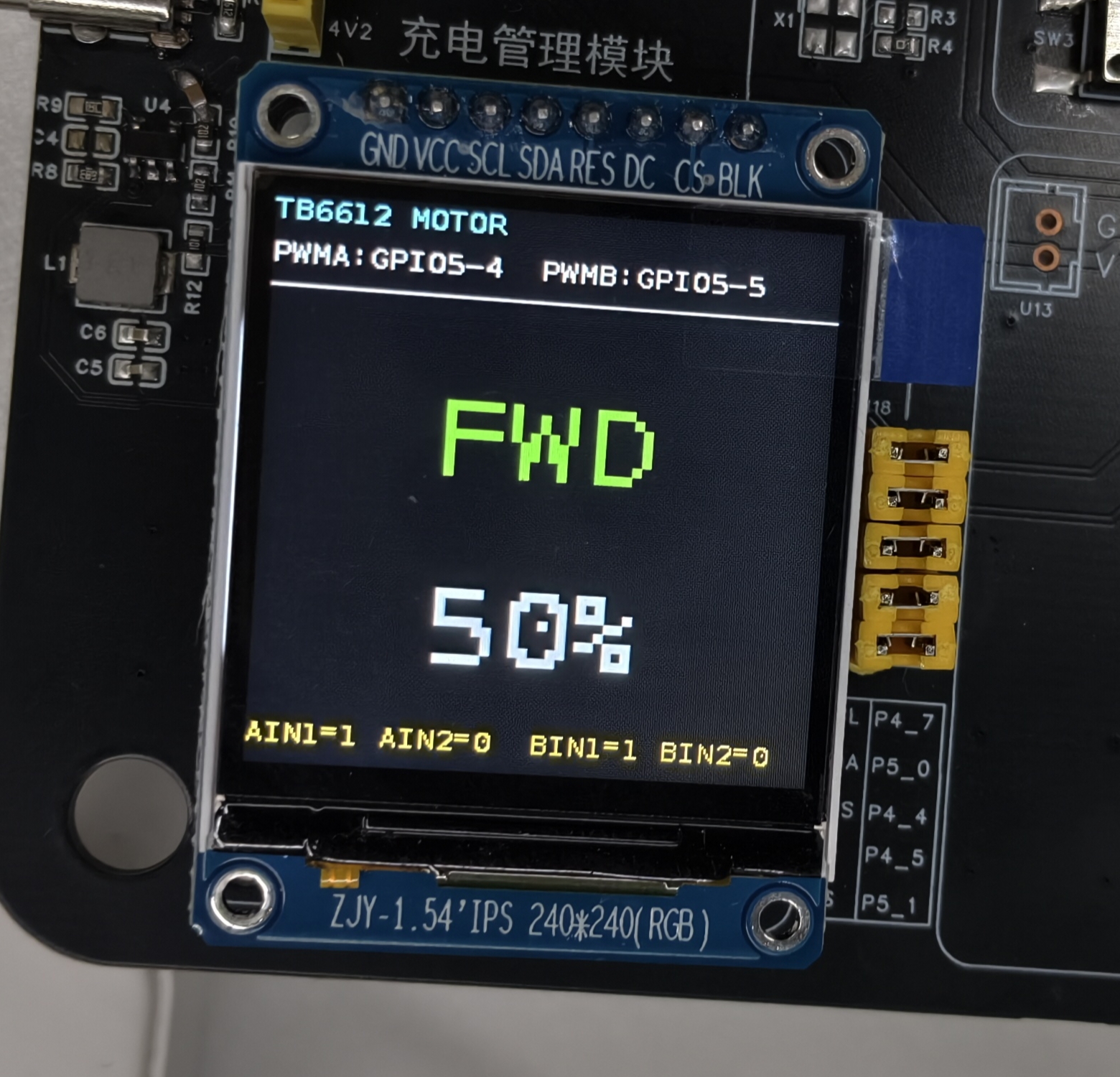
Motor control display

4 PWM Modulation Principles

4.1 PWM Basics

PWM (pulse-width modulation) controls the average voltage by changing the duty cycle of the pulses:

  • Duty cycle: the proportion of the high-level time within a full period
  • Frequency: the periodicity of the PWM signal (10 kHz recommended)
  • Resolution: the number of adjustable steps of the PWM

4.2 PWM Configuration

int pwm_export(int pin)
{
    char path[64];
    snprintf(path, sizeof(path), "/sys/class/pwm/pwmchip0/export");

    FILE *fp = fopen(path, "w");
    if (!fp) return -1;

    fprintf(fp, "%d", pin);
    fclose(fp);
    return 0;
}

int pwm_set_config(int pin, int period_ns, int duty_ns)
{
    char path[64];

    // Set the period
    snprintf(path, sizeof(path), "/sys/class/pwm/pwmchip0/pwm%d/period", pin);
    FILE *fp = fopen(path, "w");
    if (fp) {
        fprintf(fp, "%d", period_ns);
        fclose(fp);
    }

    // Set the duty cycle
    snprintf(path, sizeof(path), "/sys/class/pwm/pwmchip0/pwm%d/duty_cycle", pin);
    fp = fopen(path, "w");
    if (fp) {
        fprintf(fp, "%d", duty_ns);
        fclose(fp);
    }

    return 0;
}

4.3 Speed Regulation

Duty cycle vs. speed:

void motor_set_speed(int motor_id, int speed_percent)
{
    // Convert the speed percentage to a duty cycle
    int period_ns = 100000;  // 10 kHz period
    int duty_ns = period_ns * speed_percent / 100;

    // Set the PWM duty cycle
    if (motor_id == 0) {
        pwm_set_config(GPIO5_4, period_ns, duty_ns);  // Motor A
    } else {
        pwm_set_config(GPIO5_7, period_ns, duty_ns);  // Motor B
    }
}

5 TB6612 Control in Detail

5.1 Basic Control Functions

// Motor forward
void motor_forward(int motor_id, int speed_percent)
{
    if (motor_id == 0) {
        gpio_set_value(GPIO5_2, 0);  // AIN1 = 0
        gpio_set_value(GPIO5_3, 1);  // AIN2 = 1
        motor_set_speed(motor_id, speed_percent);
    }
}

// Motor reverse
void motor_backward(int motor_id, int speed_percent)
{
    if (motor_id == 0) {
        gpio_set_value(GPIO5_2, 1);  // AIN1 = 1
        gpio_set_value(GPIO5_3, 0);  // AIN2 = 0
        motor_set_speed(motor_id, speed_percent);
    }
}

// Motor stop
void motor_stop(int motor_id)
{
    if (motor_id == 0) {
        gpio_set_value(GPIO5_2, 0);  // AIN1 = 0
        gpio_set_value(GPIO5_3, 0);  // AIN2 = 0
        motor_set_speed(motor_id, 0);
    }
}

// Motor brake
void motor_brake(int motor_id)
{
    if (motor_id == 0) {
        gpio_set_value(GPIO5_2, 1);  // AIN1 = 1
        gpio_set_value(GPIO5_3, 1);  // AIN2 = 1
        motor_set_speed(motor_id, 0);
    }
}

5.2 Dual-Motor Control

typedef enum {
    MOTOR_STOP = 0,
    MOTOR_FORWARD,
    MOTOR_BACKWARD,
    MOTOR_BRAKE
} motor_direction_t;

void motor_control(int motor_id, motor_direction_t direction, int speed_percent)
{
    switch (direction) {
        case MOTOR_FORWARD:
            motor_forward(motor_id, speed_percent);
            break;
        case MOTOR_BACKWARD:
            motor_backward(motor_id, speed_percent);
            break;
        case MOTOR_STOP:
            motor_stop(motor_id);
            break;
        case MOTOR_BRAKE:
            motor_brake(motor_id);
            break;
    }
}

6 Key Programming Points

6.1 GPIO Initialization

int gpio_export(int pin)
{
    char buffer[64];
    snprintf(buffer, sizeof(buffer), "/sys/class/gpio/export");

    FILE *fp = fopen(buffer, "w");
    if (!fp) return -1;

    fprintf(fp, "%d", pin);
    fclose(fp);
    return 0;
}

int gpio_set_direction(int pin, const char *direction)
{
    char path[64];
    snprintf(path, sizeof(path), "/sys/class/gpio/gpio%d/direction", pin);

    FILE *fp = fopen(path, "w");
    if (!fp) return -1;

    fprintf(fp, "%s", direction);
    fclose(fp);
    return 0;
}

6.2 PWM Initialization

int pwm_enable(int pin)
{
    char path[64];
    snprintf(path, sizeof(path), "/sys/class/pwm/pwmchip0/pwm%d/enable", pin);

    FILE *fp = fopen(path, "w");
    if (!fp) return -1;

    fprintf(fp, "1");
    fclose(fp);
    return 0;
}

6.3 Smooth Speed Adjustment

void motor_smooth_speed(int motor_id, int target_speed, int step_delay)
{
    int current_speed = get_current_speed(motor_id);

    while (current_speed != target_speed) {
        if (current_speed < target_speed) {
            current_speed++;
        } else {
            current_speed--;
        }

        motor_set_speed(motor_id, current_speed);
        usleep(step_delay * 1000);
    }
}

7 Troubleshooting

ProblemPossible causeSolution
Motor does not turnWrong control signal, insufficient supplyCheck the GPIO config, verify the VM voltage
Only one directionWrong direction control signalCheck the AIN1/AIN2 states
Speed not adjustableAbnormal PWM signalCheck the PWM configuration and frequency
Motor jitterPWM frequency too lowRaise the PWM frequency above 10 kHz
Motor overheatingProlonged heavy-load operationReduce the load, improve cooling
Weak brakingWrong brake logicCheck that both AIN1/AIN2 are high

Motor usage tips

  • Power choice: use a separate battery supply; avoid powering the motor from the board
  • PWM frequency: 10 kHz is recommended, balancing noise and response speed
  • Start-up: use a smooth (ramped) start to avoid inrush current
  • Thermal design: watch the motor and driver chip temperature during long runs

8 Advanced Features

8.1 Acceleration/Deceleration Control

void motor_ramp_speed(int motor_id, int start_speed, int end_speed, int ramp_time)
{
    int steps = abs(end_speed - start_speed);
    int delay = ramp_time * 1000 / steps;

    for (int i = 0; i <= steps; i++) {
        int speed = start_speed + (end_speed - start_speed) * i / steps;
        motor_set_speed(motor_id, speed);
        usleep(delay);
    }
}

8.2 Position Control

void motor_move_steps(int motor_id, int steps, int speed_percent)
{
    int step_delay = 1000000 / (speed_percent * 10);  // Simplified calculation

    for (int i = 0; i < steps; i++) {
        motor_forward(motor_id, speed_percent);
        usleep(step_delay);
    }

    motor_stop(motor_id);
}

8.3 Current Protection

bool motor_check_current(int motor_id, float max_current)
{
    float current = read_motor_current(motor_id);

    if (current > max_current) {
        printf("[Motor] 电流过载: %.2fA\n", current);
        motor_brake(motor_id);
        return false;
    }

    return true;
}

9 References

  • GPIO Interface in Detail
  • PWM Interface in Detail
  • Servo Control Application
  • Development Environment Setup
Edit this page on GitHub
Prev
10 - SpO2 Sensor Application
Next
12 - Servo Control Application