
10 - SpO2 Sensor Application
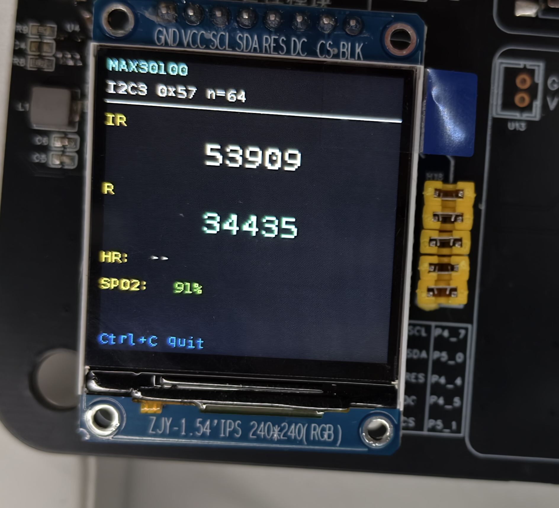
This chapter describes the MAX30100 SpO2 sensor application example — spo2_sensor — on the Pico-G1 expansion board. The application demonstrates how to read the infrared and red-light data from a MAX30100 sensor over the I2C interface, compute the heart rate and blood oxygen saturation (SpO2), and display the health data in real time on a TFT screen. It is an advanced example for learning optical sensors and signal processing.
The application source code is located in the SDK directory source/app/10_spo2_sensor/ and provides a complete implementation of I2C sensor reading and signal processing.
1 Application Overview
1.1 Features
- Optical sensor reading: reads the IR/red data of the MAX30100 over the I2C interface
- Heart-rate calculation: computes the heart rate (BPM) from infrared signal peak detection
- SpO2 estimation: estimates the blood oxygen saturation (SpO2) from the red/infrared ratio
- FIFO buffering: stores sampled data in the sensor's internal FIFO
- INT interrupt support: supports data-ready interrupt detection
1.2 Technical Specifications
| Parameter | Value |
|---|---|
I2C interface | I2C3 (/dev/i2c-3) |
Slave address | 0x57 (0x5A on some modules) |
Sample rate | 50 Hz |
ADC resolution | 16-bit |
Heart-rate range | 30~220 BPM |
SpO2 range | 70~100% |
Refresh interval | 200 ms (configurable) |
1.3 Test Case List
| index | Name | Test command | Expected result (success) | Possible causes of failure |
|---|---|---|---|---|
| 1 | Basic reading | ./spo2_sensor | TFT shows heart rate/SpO2, console prints data | I2C connection failed, wrong address |
| 2 | Finger test | Place a finger on the sensor correctly | Heart rate 60-100 BPM, SpO2 95-100% | Finger misplaced, improper pressure |
| 3 | Exercise test | Light exercise after measuring | Heart rate rises 5-20 BPM, SpO2 roughly stable | Loose sensor, signal interference |
1.4 Directory Structure
source/app/10_spo2_sensor/
├── Makefile              # Build script
├── main.c                # Main program
├── max30100.c            # MAX30100 driver implementation
├── max30100.h            # MAX30100 driver header
├── spo2_algorithm.c      # SpO2 algorithm implementation
├── spo2_algorithm.h      # SpO2 algorithm header
├── i2c_hal.c             # I2C HAL layer implementation
├── i2c_hal.h             # I2C HAL layer header
├── spi_hal.c             # SPI HAL layer implementation
├── spi_hal.h             # SPI HAL layer header
├── st7789.c              # ST7789 driver implementation
├── st7789.h              # ST7789 driver header
├── font8x16.h            # 8×16 ASCII bitmap font
└── README.md             # Documentation
2 Hardware Connection
2.1 Pin Definitions
| Signal | On-board GPIO | Control / node | Description |
|---|---|---|---|
| SCL | GPIO4_1 | I2C3 → /dev/i2c-3 | Shares the I2C3 bus with OLED/MPU6050 |
| SDA | GPIO4_2 | I2C3 → /dev/i2c-3 | Shared bus |
| INT | GPIO4_4 | Interrupt input | Data-ready interrupt (optional) |
| VCC | 3.3V | — | MAX30100 operating voltage 1.8~3.3V |
| GND | GND | — | Ground |
2.2 Hardware Circuit
MAX30100 wiring diagram:
     Pico-G1                   MAX30100 Module
  ┌───────────┐              ┌──────────────┐
  │           │              │              │
  │ GPIO4_1 ──┼────── SCL ───┤ SCL          │
  │           │              │              │
  │ GPIO4_2 ──┼────── SDA ───┤ SDA          │
  │           │              │              │
  │ GPIO4_4 ──┼────── INT ───┤ INT          │
  │           │              │              │
  │    3.3V ───┼─────────────┤ VCC          │
  │           │              │              │
  │     GND ───┼─────────────┤ GND          │
  └───────────┘              └──────────────┘
Medical disclaimer
This example is for learning and demonstration only and is not suitable for medical diagnosis. Professional medical devices require rigorous calibration and certification.
3 Build and Deployment
3.1 Build the Application
export PATH=$PATH:<SDK>/tools/linux/toolchains/arm-gcc12.2.0-linux-uclibceabi/bin
cd <SDK>/source/app/10_spo2_sensor
make
3.2 Run the Application
scp spo2_sensor root@<board_ip>:/usr/bin/
ssh root@<board_ip> '/usr/bin/spo2_sensor'
3.3 Expected Output
Console output
/mnt # ./spo2_sensor
[max] pad 复用:I2C3(4_1/4_2)->func2,GPIO4_4->func5
[max] pad 0x100C0010 -> 0x00001002
[max] pad 0x100C0014 -> 0x00001002
[max] 初始化 SPI 屏(/dev/spidev2.0)...
[spi] pad 0x100C0028 -> 0x00001004
[spi] pad 0x100C002C -> 0x00001004
[spi] pad 0x100C0030 -> 0x00001000
[spi] pad 0x100C0020 -> 0x00001005
[spi] pad 0x100C001C -> 0x00001005
[spi] opening /dev/spidev2.0 ...
[spi] spidev opened, fd=3
[spi] spidev mode/bits/speed set (MODE3/8b/24MHz)
[spi] chardev request DC  @ /dev/gpiochip4 line 5 ...
[spi] chardev request RES @ /dev/gpiochip4 line 4 ...
[spi] chardev request CS  @ /dev/gpiochip5 line 1 ...
[spi] chardev-verify: DC=0(expect0) RES=1(expect1) CS=1(expect1)  ==> OK(chardev 真驱动了引脚)
[spi] spi_hal_init done
[tft] init: SLPOUT
[tft] init: SLPOUT +120ms ok
[tft] init: config cmds ok
[tft] init: DISPON
[tft] init: DISPON ok
[tft] init: clear-flush start
[tft] flush #1 start
[tft] flush #1 done
[tft] init: clear-flush done
[max] 初始化 MAX30100(/dev/i2c-3 addr 0x57)...
[max] PART_ID=0x11 REV_ID=0x05
[max] @ /dev/i2c-3 addr 0x57 (rev=0x05, INT=disabled, polling only)
[max] 采集中,50 SPS;采样线程 100ms/次,屏刷 200ms/次,Ctrl+C 退出。
TFT screen display
4 MAX30100 Sensor Principles
4.1 I2C Register Configuration
Main registers:
| Register address | Name | Description |
|---|---|---|
| 0x02 | MODE_REGISTER | Operating mode config |
| 0x03 | SPO2_REGISTER | SpO2 mode config |
| 0x04 | LED_REGISTER | LED current control |
| 0x05 | FIFO_REGISTER | FIFO configuration |
| 0x06 | FIFOdatapointer | FIFO data pointer |
| 0x07 | FIFO_READ | FIFO data read |
4.2 FIFO Read/Write Mechanism
The MAX30100 has a built-in 16-byte FIFO buffer:
// Configure the FIFO
void max30100_config_fifo(int i2c_fd)
{
    uint8_t fifo_config = 0x00;  // Sample averaging settings
    i2c_write_register(i2c_fd, MAX30100_ADDR, 0x05, &fifo_config, 1);

    // Set the FIFO watermark
    uint8_t sample_avg = 0x01;  // Average every 2 samples
    i2c_write_register(i2c_fd, MAX30100_ADDR, 0x05, &sample_avg, 1);
}

// Read FIFO data
void max30100_read_fifo(int i2c_fd, uint8_t *data, uint8_t len)
{
    i2c_write_register(i2c_fd, MAX30100_ADDR, 0x06, NULL, 0);  // Set the FIFO pointer
    i2c_read_bytes(i2c_fd, MAX30100_ADDR, 0x07, data, len);   // Read the data
}
4.3 Data Format
MAX30100 output data format:
- IR (infrared): 16-bit ADC value
- R (red): 16-bit ADC value
- Per frame: 4 bytes (IR_L + IR_H + R_L + R_H)
5 Heart Rate & SpO2 Computation
5.1 Heart-Rate Algorithm
Signal processing flow:
// Heart-rate calculation steps
float calculate_heart_rate(uint16_t *ir_buffer, int buffer_size)
{
    // 1. Compute the baseline and amplitude
    float baseline = calculate_baseline(ir_buffer, buffer_size);
    float amplitude = calculate_amplitude(ir_buffer, buffer_size, baseline);

    // 2. Set the detection threshold
    float threshold = baseline + amplitude * 0.3f;

    // 3. Detect peaks
    int peak_count = 0;
    float peak_intervals[16];
    for (int i = 1; i < buffer_size - 1; i++) {
        if (ir_buffer[i] > threshold &&
            ir_buffer[i] > ir_buffer[i-1] &&
            ir_buffer[i] > ir_buffer[i+1]) {
            // Record the peak interval
            if (peak_count > 0) {
                peak_intervals[peak_count-1] = i * 0.02f;  // 50 Hz sampling
            }
            peak_count++;
        }
    }

    // 4. Compute the average interval
    float avg_interval = 0;
    for (int i = 0; i < peak_count - 1; i++) {
        avg_interval += peak_intervals[i];
    }
    avg_interval /= (peak_count - 1);

    // 5. Compute the heart rate
    return 60.0f / avg_interval;  // BPM
}
5.2 SpO2 Estimation Algorithm
Ratio method:
float calculate_spo2(uint16_t *ir_buffer, uint16_t *red_buffer, int buffer_size)
{
    // 1. Compute the mean of IR and R
    float ir_avg = 0, red_avg = 0;
    for (int i = 0; i < buffer_size; i++) {
        ir_avg += ir_buffer[i];
        red_avg += red_buffer[i];
    }
    ir_avg /= buffer_size;
    red_avg /= buffer_size;

    // 2. Compute the ratio
    float ratio = (red_avg / ir_avg);

    // 3. Estimate SpO2 (simplified formula)
    float spo2 = 110.0f - 30.0f * ratio;

    // 4. Clamp the range
    if (spo2 > 100.0f) spo2 = 100.0f;
    if (spo2 < 70.0f) spo2 = 70.0f;

    return spo2;
}
6 Key Programming Points
6.1 MAX30100 Initialization
int max30100_init(int i2c_fd)
{
    // Reset the sensor
    uint8_t mode_config = 0x03;  // Reset
    i2c_write_register(i2c_fd, MAX30100_ADDR, 0x02, &mode_config, 1);
    usleep(10000);  // Wait for the reset to finish

    // Configure SpO2 mode
    uint8_t spo2_config = 0x4F;  // 50 Hz sampling, 16-bit ADC
    i2c_write_register(i2c_fd, MAX30100_ADDR, 0x03, &spo2_config, 1);

    // Configure the LED current
    uint8_t led_config = 0x4F;  // IR and R both at 50 mA
    i2c_write_register(i2c_fd, MAX30100_ADDR, 0x04, &led_config, 1);

    return 0;
}
6.2 Signal Acquisition
#define BUFFER_SIZE 100

typedef struct {
    uint16_t ir_buffer[BUFFER_SIZE];
    uint16_t red_buffer[BUFFER_SIZE];
    int buffer_index;
} signal_buffer_t;

void collect_samples(int i2c_fd, signal_buffer_t *signals)
{
    uint8_t fifo_data[4];

    // Read the FIFO
    max30100_read_fifo(i2c_fd, fifo_data, 4);

    // Parse the data
    uint16_t ir_value = (fifo_data[0] << 8) | fifo_data[1];
    uint16_t red_value = (fifo_data[2] << 8) | fifo_data[3];

    // Store into the buffer
    if (signals->buffer_index < BUFFER_SIZE) {
        signals->ir_buffer[signals->buffer_index] = ir_value;
        signals->red_buffer[signals->buffer_index] = red_value;
        signals->buffer_index++;
    }
}
6.3 Data Calibration
Signal quality check:
bool check_signal_quality(uint16_t *ir_buffer, int buffer_size)
{
    // Compute the signal range
    uint16_t min_val = 0xFFFF, max_val = 0;
    for (int i = 0; i < buffer_size; i++) {
        if (ir_buffer[i] < min_val) min_val = ir_buffer[i];
        if (ir_buffer[i] > max_val) max_val = ir_buffer[i];
    }

    uint16_t amplitude = max_val - min_val;

    // Signal amplitude check
    if (amplitude < 100) {
        printf("[SPO2] 信号强度不足\n");
        return false;
    }

    return true;
}
7 Troubleshooting
| Problem | Possible cause | Solution |
|---|---|---|
| Abnormal readings | Finger misplaced | Make sure the finger fully covers the sensor with moderate pressure |
| Heart rate 0 | Weak signal, detection algorithm failure | Adjust the LED current, check ambient light interference, reposition the finger |
| Abnormal SpO2 values | Wrong ratio computation, calibration issues | Recalibrate the sensor, keep the finger still |
| Data not updating | Wrong FIFO config, I2C communication failed | Check the sensor register configuration, verify the I2C connection |
| Jumpy heart rate | Finger movement, environmental interference | Keep the finger still, avoid strong direct light |
Measurement tips
For best measurement results:
- Finger placement: use the index or middle finger, resting lightly on the sensor
- Stay still: keep the hand steady during measurement and avoid movement
- Ambient light: avoid shining strong light directly on the sensor
- Measurement duration: at least 5 seconds per measurement
8 Advanced Features
8.1 Signal Filtering
Low-pass filter:
#define ALPHA 0.1f  // Filter coefficient

float low_pass_filter(float input, float prev_output)
{
    return ALPHA * input + (1.0f - ALPHA) * prev_output;
}
8.2 Data Trend Analysis
typedef struct {
    float history[10];
    int index;
} spo2_history_t;

void update_spo2_history(spo2_history_t *history, float spo2)
{
    history->history[history->index] = spo2;
    history->index = (history->index + 1) % 10;

    // Compute the trend
    float avg = 0;
    for (int i = 0; i < 10; i++) {
        avg += history->history[i];
    }
    avg /= 10.0f;

    printf("[SPO2] 当前: %.1f%% 平均: %.1f%%\n", spo2, avg);
}
8.3 Bluetooth Data Transfer
// Send data to a phone app
void send_spo2_via_bluetooth(float heart_rate, float spo2)
{
    char buffer[64];
    snprintf(buffer, sizeof(buffer), "HR:%.0f,SPO2:%.1f", heart_rate, spo2);

    // Send the data over BLE
    bluetooth_send(buffer, strlen(buffer));
}