
14 MTCNN Face Detection Application
This chapter describes a complete face detection application example based on the GK7206 NPU — face_recognize. The application uses the MTCNN (Multi-task Cascaded Convolutional Networks) three-stage cascaded network to perform real-time face detection and landmark localization on the board, and provides a browser visualization UI through an embedded web server.
The application source code is located in the SDK directory app_sample/face_recognize/. It is a standalone, self-contained example project covering the complete chain of video capture, NPU inference, and web display, suitable as a reference template for developing custom AI vision applications.
1 Application Overview
1.1 Features
- MTCNN three-stage cascaded detection: P-Net (coarse screening) → R-Net (fine screening) → O-Net (landmarks), filtering face candidate boxes stage by stage
- 5-point facial landmark localization: left eye, right eye, nose tip, left mouth corner, right mouth corner
- Real-time web visualization: embedded HTTP server; view the MJPEG video stream and detection overlay directly in a browser
- Inter-frame tracking stability: IoU-based inter-frame face tracking + EMA smoothing, eliminating detection box jitter
- Image pyramid multi-scale detection: supports face detection at different scales
1.2 Technical Parameters
| Parameter | Value |
|---|---|
Sensor resolution | 2560 × 1440 (SC465SL) |
Detection input resolution | 320 × 180 (16:9, matching the sensor aspect ratio) |
NPU inference frame rate | ~8 FPS (limited by the P-Net sliding window count) |
Web service port | 80 |
Video encoding format | MJPEG |
Model format | .xmm (GK7206 NPU-specific format) |
Minimum face size | 48 × 48 pixels (in the detection image) |
Cascade thresholds | P-Net: 0.50 / R-Net: 0.70 / O-Net: 0.30 |
1.3 Directory Structure
app_sample/face_recognize/
├── Makefile                  # Build script
├── src/
│   └── main.c               # Main program (~1800 lines, NPU inference + web service)
├── models/
│   ├── pnet.xmm             # P-Net model (coarse screening, input 12×12)
│   ├── rnet.xmm             # R-Net model (fine screening, input 24×24)
│   └── onet.xmm             # O-Net model (landmarks, input 48×48)
└── web/
    ├── index.html            # Web frontend page
    ├── app.js                # Frontend logic (API polling, drawing detection boxes)
    └── style.css             # Page style
1.4 Common Module
The application depends on the common modules in the app_sample/common/ directory:
app_sample/common/
├── web_server.h                 # Web server header file
└── web_server.c                 # Lightweight HTTP server implementation
The web_server module provides:
| Function | API | Description |
|---|---|---|
| Static file service | web_send_file() | Serves HTML/CSS/JS and other static files from the /www/ directory |
| JSON responses | web_send_json_ok() | Sends HTTP responses in JSON format |
| MJPEG streaming | web_mjpeg_send_stream() | Pushes the MJPEG video stream via callback functions |
| Custom routes | web_route_handler | Handles project-specific API requests via callback functions |
| Snapshot service | web_snapshot_handler | Returns JPEG snapshots via callback functions |
Web Server Configuration
Key configuration parameters (defined in web_server.h):
WEB_LISTEN_PORT = 80: HTTP service portWEB_WWW_ROOT = "/www": static file root directoryWEB_BACKLOG = 8: maximum number of concurrent connections
2 Build and Deployment
2.1 Prerequisites
Before building this application, make sure the following preparations are complete:
- SDK environment ready: set up the cross-compilation toolchain and SDK configuration by following SDK Build
- SDK fully built once: the application depends on the SDK's common libraries and headers, so a full build must be executed first to generate the
out/directory - Board driver loaded: make sure the NPU kernel module
xm_npu.kois loaded
2.2 Build the Application
Enter the application directory and build directly with the SDK build system:
# Enter the application directory
cd <SDK_PATH>/app_sample/face_recognize

# Build (the SDK Makefile automatically uses the cross-compilation toolchain)
make clean && make
How the Build Works
The Makefile includes the SDK build rules via include $(SDK_DIR)/build/base.mk and include $(SAMPLE_DIR)/sample_base.mk, which automatically configure the cross compiler, header file paths, and linked libraries. There is no need to set up the toolchain manually.
After a successful build, the executable face_recognize is generated in the current directory.
2.3 Deploy to the Board
Info
The application binary is fairly large, so mount an SD card before running it.
mkdir -p /sd_card
mount /dev/mmcblk1p1 /sd_card
Transfer the following files to the development board via SCP:
Directory Structure Requirements
- The web frontend files must be placed in the board's
/www/directory (the default static file rootWEB_WWW_ROOTof theweb_servermodule) - The models files must be placed in the application's working directory
# Execute on the development host
# 1. Create the board application directory
ssh root@<board IP> "mkdir -p /sd_card/models /www"

# 2. Transfer the executable
scp face_recognize root@<board IP>:/sd_card/

# 3. Transfer the model files
scp -Or models root@<board IP>:/sd_card/

# 4. Transfer the web frontend files
scp web/* root@<board IP>:/www/
2.4 Run the Application
# Enter the application directory
cd /sd_card

# Add execute permission (first time)
chmod +x face_recognize

# Run
./face_recognize
After startup, the terminal prints the following log:
=== MTCNN Face Detection for GK7206 ===
[init] sensor: 2560x1440 @ 30fps
[npu] Initializing...
[npu] Found 1 device(s)
[npu] Loading P-Net...
[npu] ./models/pnet.xmm loaded
[npu] Loading R-Net...
[npu] ./models/rnet.xmm loaded
[npu] Loading O-Net...
[npu] ./models/onet.xmm loaded
[npu] All models loaded!
[init] Pipeline: VI→VPSS→VENC(MJPEG) + VPSS→NPU(320x180 MTCNN)
[main] System ready. Open http://<board-ip>/ in browser
2.5 Browser Access
Open http://<board IP>/ in a desktop browser to see the live face detection picture:
- The center of the page shows the MJPEG video stream
- Detected faces are marked with green rectangles
- The confidence percentage is shown above each face box
- Facial landmarks (5 points) are marked with blue dots connected by dashed lines
- The status bar at the bottom shows the detection FPS and the current face count
2.6 Stop the Application
Press Ctrl+C in the terminal to send the SIGINT signal and exit gracefully. The application stops the NPU inference thread, unloads the models, and releases the video pipeline resources in order.
Note
If Ctrl+C fails to exit gracefully or takes too long, find the PID of the ./face_recognize process and force-terminate it:
ps | grep face_recognize
kill -9 <PID>
3 System Architecture
3.1 Overall Data Flow
The overall architecture follows the classic embedded AI vision pipeline of "video capture → pre-processing → NPU inference → web display":

3.2 Thread Model
The application adopts a multi-threaded architecture with the following thread responsibilities:
| Thread | Responsibility | Key operations |
|---|---|---|
| Main thread | Runs the web server (blocking loop) | Receives HTTP requests, dispatches routes, pushes the MJPEG stream |
| NPU inference thread | Acquires frames and runs MTCNN in a loop | VPSS frame acquisition → YUV→RGB → MTCNN → update detection results |
| ISP thread (inside the SDK) | Image signal processing | 3A (AE/AWB/AF), noise reduction, color correction |
Threads share the detection results (g_faces array and g_face_count) protected by the pthread_mutex_t g_face_mutex mutex, ensuring data consistency between the NPU thread's writes and the HTTP thread's reads.
4 Internal Execution Logic
4.1 Startup Flow
The main() function starts in 5 stages:
// Stage 1: initialize the video pipeline (VI → VPSS → VENC)
init_system();

// Stage 2: initialize the NPU (load the 3 MTCNN models)
init_npu();

// Stage 3: start the NPU inference thread
g_npu_running = XMEDIA_TRUE;
pthread_create(&g_npu_thread, NULL, npu_inference_thread, NULL);

// Stage 4: register the MJPEG handler and start the web server (blocking)
web_server_set_mjpeg_handler(mjpeg_send_stream, mjpeg_request_stop);
web_server_run(project_route_get);

// Stage 5: clean up resources at shutdown
g_npu_running = XMEDIA_FALSE;
pthread_join(g_npu_thread, NULL);
deinit_npu();
deinit_system();
4.2 Video Pipeline Initialization
init_system() initializes the MPP video pipeline in the following order:
System initialization: configure the VB (Video Buffer) memory pools
- Pool 0: VI capture buffers (full resolution)
- Pool 1: VPSS full-resolution / VENC encoding buffers
- Pool 2: VPSS NPU input buffers (320 × 180)
Module initialization: initialize the VI, VPSS, and VENC modules in order
ISP initialization: configure image signal processing parameters (frame rate, pixel format, resolution, etc.)
VI start: start video input, acquiring images from the sensor
VPSS configuration: configure two output channels
ochn0: full-resolution output → sent to VENC for MJPEG encodingochn1: scaled to 320 × 180 → sent to NPU inference
Binding:
VI → VPSS → VENC
VI(pipe=0, chn=0) ──bind──→ VPSS(pipe=0, ochn=0) ──bind──→ VENC(chn=0, MJPEG)
                          └→ VPSS(pipe=0, ochn=1) ──manual acquire──→ NPU inference thread
NPU Frame Acquisition Method
VENC automatically acquires VPSS output frames via bind mode, while the NPU inference thread manually acquires frames from VPSS ochn1 with xmedia_vpss_acquire_ochn_frame(). This is because NPU inference is slower than the video frame rate and unsuitable for bind mode.
4.3 NPU Model Loading
The init_npu() function loads the 3 MTCNN models. Each model is loaded as follows:
// 1. Query the memory size required by the model
xmedia_cl_graph_querysize_from_file(path, &worksize, &weightsize);

// 2. Allocate MMZ memory (physically contiguous; required for NPU DMA access)
mmz_alloc_map("npu_work",  &work_phy,  &work_buf,  worksize);
mmz_alloc_map("npu_weight", &weight_phy, &weight_buf, weightsize);

// 3. Load the model onto the NPU
xmedia_cl_graph_loadmodel_from_file_withmem(&ctx, path,
    work_buf, worksize, weight_buf, weightsize, &graph);

// 4. Get input/output tensor info (two queries: the first gets counts, the second gets details)
xmedia_cl_graph_get_input(graph, 0, &input);           // 1st: get the count
input.tensor = malloc(sizeof(...) * input.num);
xmedia_cl_graph_get_input(graph, input.num, &input);   // 2nd: get the details

// 5. Allocate input/output buffers
mmz_alloc_map("npu_in",  &input_phy,  &input_buf,  inputsize);
mmz_alloc_map("npu_out", &output_phy, &output_buf, outputsize);

// 6. Set tensor addresses and bind
xmedia_cl_graph_set_inout(graph, &input, &output);
Memory Allocation Note
Buffers accessed by the NPU (workspace, weight, input, output) must be allocated with xmedia_mmz_alloc() as physically contiguous memory (MMZ), not ordinary malloc(). This is because the NPU accesses physical memory directly via DMA.
The specifications of the three MTCNN models:
| Model | Input size | Output Tensor | Description |
|---|---|---|---|
| P-Net | [1, 3, 12, 12] | score(2ch) + bbox(4ch) | Coarse screening network; extracts candidates via image pyramid + sliding window |
| R-Net | [1, 3, 24, 24] | score(2ch) + bbox(4ch) | Fine screening network; crops and infers per candidate |
| O-Net | [1, 3, 48, 48] | score(2ch) + bbox(4ch) + landmark(10ch) | Output network; refinement + 5-point landmarks |
4.4 NPU Inference Thread
npu_inference_thread() is the core inference loop, executing the following steps per frame:
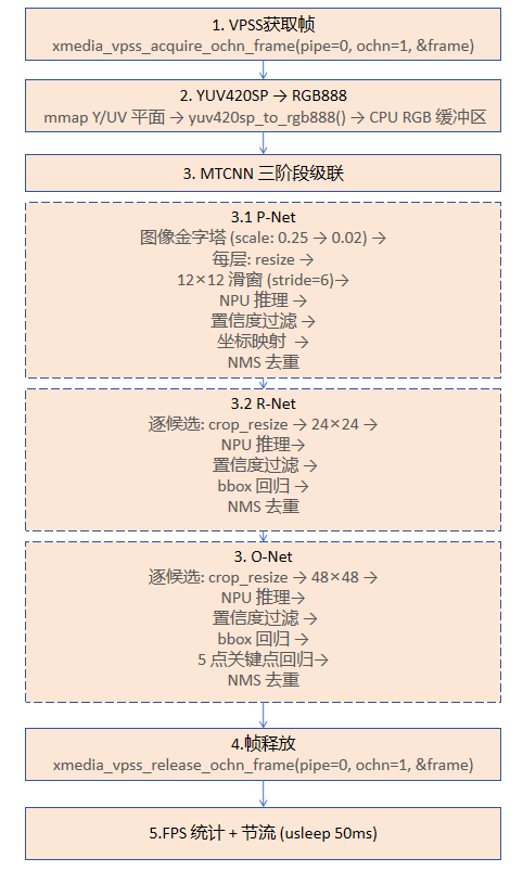
4.5 MTCNN Detection Algorithm Details
4.5.1 P-Net: Image Pyramid + Sliding-Window Detection
P-Net is a fully convolutional network that takes 12 × 12 image patches and decides whether they contain a face. Since faces vary in size, an image pyramid is built for multi-scale detection:
// Build the pyramid: start from 12/min_face_size, shrink layer by layer
scale = (float)PNET_PATCH_SIZE / PNET_MIN_FACE_SIZE;  // initial: 12/48 = 0.25

while (scaled_image >= 12×12) {
    resize_rgb(src, DET_WIDTH, DET_HEIGHT, scaled, sw, sh);

    // Sliding-window scan
    for (y = 0; y <= sh - 12; y += PNET_STRIDE) {
        for (x = 0; x <= sw - 12; x += PNET_STRIDE) {
            // Extract a 12×12 patch → NPU inference → confidence filtering
            // Map coordinates back to the original image + bbox regression
        }
    }

    scale *= PNET_SCALE_FACTOR;  // 0.707 (= 1/√2, standard MTCNN)
}
Key parameter descriptions:
| Parameter | Value | Description |
|---|---|---|
PNET_PATCH_SIZE | 12 | P-Net input size |
PNET_STRIDE | 6 | Sliding window stride; 6=fast, 4=balanced, 2=best recall |
PNET_MIN_FACE_SIZE | 48 | Minimum detectable face size (pixels in the detection image) |
PNET_SCALE_FACTOR | 0.707 | Pyramid scale factor (1/√2) |
FACE_CONF_THRESHOLD | 0.50 | P-Net confidence threshold |
4.5.2 R-Net: Candidate Fine Screening
R-Net takes the candidate boxes output by P-Net, crops the corresponding regions from the original image, scales them to 24 × 24, and performs a second screening:
for (i = 0; i < pnet_count; i++) {
    // 1. Crop the candidate region and scale it to 24×24
    crop_resize(rgb_img, DET_WIDTH, DET_HEIGHT, &cands[i], crop, 24);

    // 2. Copy to the model input (handling the NCHW layout)
    copy_rgb_to_model_input(&g_rnet, crop, 24, 24);

    // 3. NPU inference
    xmedia_cl_graph_process(g_rnet.graph);

    // 4. Dequantization + confidence filtering + bbox regression
    dequantize_output(&g_rnet, score_idx, s_vals, 2);
    dequantize_output(&g_rnet, box_idx, b_vals, 4);

    if (prob >= 0.70f) {  // R-Net threshold is higher, stricter filtering
        bbox_reg(&cands[out_count], b_vals);
        out_count++;
    }
}
// NMS deduplication
out_count = nms(cands, out_count, 0.50f);
4.5.3 O-Net: Final Refinement + Landmarks
O-Net further refines the box positions on top of R-Net and outputs 5 facial landmarks:
for (i = 0; i < rnet_count; i++) {
    // Crop → 48×48 → NPU inference
    crop_resize(rgb_img, DET_WIDTH, DET_HEIGHT, &cands[i], crop, 48);
    copy_rgb_to_model_input(&g_onet, crop, 48, 48);
    xmedia_cl_graph_process(g_onet.graph);

    // Dequantization: score(2) + bbox(4) + landmark(10)
    dequantize_output(&g_onet, score_idx, s_vals, 2);
    dequantize_output(&g_onet, box_idx, b_vals, 4);
    dequantize_output(&g_onet, lm_idx, l_vals, 10);

    // Landmark regression (the model outputs planar format: [x0..x4, y0..y4])
    for (k = 0; k < 5; k++) {
        landmarks[k*2]     = x1 + l_vals[k]     * bw;  // X coordinate
        landmarks[k*2 + 1] = y1 + l_vals[5 + k] * bh;  // Y coordinate
    }
}
Landmark order: left eye (LE) → right eye (RE) → nose tip (N) → left mouth corner (ML) → right mouth corner (MR).
4.6 Post-processing and Inter-frame Tracking
Shape Filtering
After NMS, filter_implausible() filters implausible detection boxes with the following heuristic rules:
// Reject boxes that are not face-shaped
- Aspect ratio < 0.20 or > 3.0 (note: quantized MTCNN bbox regression systematically narrows boxes)
- Width or height < 6 pixels (too small)
- Area > 90% of the detection image (too large)
Inter-frame Tracking
update_tracks() implements simple IoU-based inter-frame tracking, used to:
- Stabilize the display: smooth detection box positions with EMA (exponential moving average), eliminating inter-frame jitter
- Delayed disappearance: when a face is temporarily occluded or detection is lost, keep showing it for several frames (
MAX_MISS = 3) - Unique ID: each track is assigned a unique ID
// Per-frame processing flow:
// 1. Match new detections against existing tracks using IoU
// 2. Matched → EMA-smooth position update
//    Not matched → create a new track, or miss_count++
// 3. miss_count > MAX_MISS → remove the track
4.7 Output Quantization and Dequantization
The NPU outputs INT8 quantized data, which must be dequantized to floating point before use:
// Dequantization formula
float_value = (int8_value - zero_point) × scale

// Implementation
static void dequantize_output(const npu_model_t *m, int tensor_idx,
                              float *out, int count)
{
    unsigned char *data = get_output_data(m, tensor_idx);
    float scale = m->output.tensor[tensor_idx].quant.scale;
    int zp = m->output.tensor[tensor_idx].quant.zp;
    for (i = 0; i < count; i++)
        out[i] = ((float)data[i] - zp) * scale;
}
4.8 Web Service and API
The application embeds a lightweight HTTP server (web_server.c) that provides the following routes:
| Route | Method | Function |
|---|---|---|
/ | GET | Serves the index.html page |
/mjpeg | GET | MJPEG video stream (multipart/x-mixed-replace) |
/api/faces | GET | Returns the detection results in JSON format |
/api/status | GET | Returns brief status information |
/style.css, /app.js | GET | Static resource files |
JSON format returned by /api/faces:
{
  "count": 2,
  "fps": 18,
  "faces": [
    {
      "x": 0.3125,
      "y": 0.2056,
      "w": 0.1875,
      "h": 0.3333,
      "score": 0.998,
      "landmarks": [
        { "x": 0.35, "y": 0.29 },
        { "x": 0.44, "y": 0.285 },
        { "x": 0.395, "y": 0.34 },
        { "x": 0.36, "y": 0.41 },
        { "x": 0.43, "y": 0.405 }
      ]
    }
  ]
}
All coordinate values are normalized to the 0.0 ~ 1.0 range (relative to the detection image size).
5 How to Write a Similar Application
This section uses face_recognize as a reference template to explain how to develop a custom AI vision application based on the GK7206 NPU.
5.1 Development Steps Overview
Step 1: Prepare the model → train/download a model → convert to .xmm format with the XMTVM tool
Step 2: Create the project → copy the Makefile template → write main.c
Step 3: Initialize the pipeline → VI + VPSS + VENC configuration
Step 4: Load the model → load .xmm via the xmedia_cl_* APIs
Step 5: Inference loop → acquire frame → pre-process → NPU inference → post-process
Step 6: Output results → web display / RTSP streaming / other means
5.2 Step 1: Prepare the Model
Use the XMTVM model conversion tool to convert a trained model (ONNX/PyTorch) into the GK7206 NPU-specific .xmm format:
# Example: convert a model with the XMTVM tool
python3 convert.py --model yolov5s.onnx \
    --input_shape 1,3,320,180 \
    --input_format RGB \
    --quantize int8 \
    --output model.xmm
Model Conversion Notes
- The model's
input_formatsetting determines the input data format (RGB/YUV, etc.) - The quantization method (INT8/UINT8) affects inference accuracy and the post-processing dequantization parameters
- Specifying
(pixel - 127.5) / 128normalization in the YAML configuration lets the NPU do it internally, reducing CPU load
5.3 Step 2: Create the Project
Create a new project following the face_recognize directory structure:
mkdir -p my_app/src my_app/models my_app/webWrite the Makefile (copy face_recognize/Makefile and modify it):
ifeq ($(CFG_SDK_EXPORT_FLAG),)
        SDK_DIR := $(shell cd $(CURDIR)/../.. && /bin/pwd)
endif

include $(SDK_DIR)/build/base.mk
include $(SAMPLE_DIR)/sample_base.mk

TARGET := my_app                    # Change to your application name

LIBS := -lxmedia_svp -lxmedia_npu $(SAMPLE_LIBS) $(SAMPLE_COMMON_LIB) -lpthread

INCLUDES := $(SAMPLE_INCLUDES)
INCLUDES += -I$(SDK_DIR)/app_sample/common    # If using web_server.c

CFLAGS := $(SAMPLE_CFLAGS) $(LIBS) $(INCLUDES)

SRCS := $(wildcard src/*.c) $(SDK_DIR)/app_sample/common/web_server.c
OBJS := $(patsubst %.c, %.o, $(SRCS))

.PHONY: all clean

all: $(OBJS)
	$(AT)$(CC) -o $(TARGET) $^ $(CFLAGS)

%.o : %.c
	$(AT)$(CC) -c -o $@ $< $(CFLAGS)

clean:
	$(AT)rm -rf $(OBJS) $(TARGET)
5.4 Step 3: Initialize the Video Pipeline
The pipeline initialization code can reuse the init_system() function framework of face_recognize; adjust the following parameters for your needs:
// 1. Adjust the NPU detection resolution to your model's input size
#define DET_WIDTH   320     // Match the model input width
#define DET_HEIGHT  180     // Match the model input height

// 2. VB memory pool configuration (3 pools)
//    - Pool 0: VI capture buffers
//    - Pool 1: VPSS full resolution / VENC
//    - Pool 2: VPSS NPU input (DET_WIDTH × DET_HEIGHT)

// 3. VPSS output channel configuration
//    - ochn0: full resolution → VENC (for web display)
//    - ochn1: scaled to DET_WIDTH×DET_HEIGHT → NPU inference
5.5 Step 4: Load the NPU Model
The model loading code can reuse the load_one_model() function, which encapsulates the complete loading flow:
// Define the model struct (encapsulates graph + tensor + buffers)
typedef struct {
    xmedia_cl_graph graph;
    xmedia_cl_tensor_info_inout input;
    xmedia_cl_tensor_info_inout output;
    void *work_buf, *weight_buf, *input_buf, *output_buf;
    xmedia_u64 work_phy, weight_phy, input_phy, output_phy;
} npu_model_t;

// Load the model
npu_model_t my_model;
load_one_model(&my_model, g_cl_ctx, "./models/my_model.xmm");
5.6 Step 5: Write the Inference Loop
The core pattern of the inference loop is "acquire frame → pre-process → NPU inference → post-process":
void *inference_thread(void *arg)
{
    while (running) {
        // 1. Acquire a frame from VPSS
        xmedia_vpss_acquire_ochn_frame(pipe, ochn, &frame, timeout);

        // 2. Pre-process (depending on the model's needs)
        //    - mmap the frame data to user space
        //    - YUV → RGB conversion (if the model needs RGB)
        //    - resize / crop to the model input size
        //    - handle the data layout (HWC → NCHW, etc.)
        void *frame_y  = xmedia_mmz_map(frame.addr.y_phy_addr, ...);
        void *frame_uv = xmedia_mmz_map(frame.addr.c_phy_addr, ...);
        yuv420sp_to_rgb888(frame_y, frame_uv, rgb_buf, ...);
        copy_rgb_to_model_input(&model, rgb_buf, width, height);

        // 3. Run NPU inference
        xmedia_cl_graph_process(model.graph);

        // 4. Post-process
        //    - read the output buffer and dequantize
        dequantize_output(&model, tensor_idx, output, count);
        //    - parse detection results (NMS, threshold filtering, etc.)
        //    - update shared state (with lock protection)

        // 5. Release the frame
        xmedia_vpss_release_ochn_frame(pipe, ochn, &frame);
        xmedia_mmz_unmap(frame_y);
        xmedia_mmz_unmap(frame_uv);
    }
}
5.7 Key Programming Points
MMZ Memory Management
NPU-related buffers must be allocated from MMZ (Media Memory Zone) as physically contiguous memory:
// Allocate + map
xmedia_u64 phy = xmedia_mmz_alloc(mmz_name, buf_name, size);
void *virt = xmedia_mmz_map(phy, size, cached);

// After use
xmedia_mmz_unmap(virt);
xmedia_mmz_free(phy);
Data Layout Conversion
NPU models usually use the NCHW layout [1, C, H, W], while camera RGB output is HWC. copy_rgb_to_model_input() detects the model layout and converts automatically:
if (model_input_is_nchw(m)) {
    // HWC → NCHW: split into R/G/B channel planes
    for (c = 0; c < 3; c++)
        for (y = 0; y < h; y++)
            for (x = 0; x < w; x++)
                dst[c*plane + y*w + x] = src[(y*w + x)*3 + c];
} else {
    memcpy(dst, src, w * h * 3);  // copy directly
}
Quantized Output Handling
The NPU outputs quantized integer data, which must be dequantized using the output tensor's quantization parameters (scale and zero_point):
float scale = m->output.tensor[idx].quant.scale;
int zp = m->output.tensor[idx].quant.zp;
float value = (float)(int8_data[i] - zp) * scale;
Output Tensor Indexing
When a model has multiple output tensors, identify each output's meaning by its channel count:
// Find the corresponding tensor index by output channel count
int score_idx = find_output_by_ch(&model, 2);    // 2 channels = classification score
int box_idx   = find_output_by_ch(&model, 4);    // 4 channels = bbox regression
int lm_idx    = find_output_by_ch(&model, 10);   // 10 channels = 5-point landmarks
5.8 Troubleshooting
| Problem | Possible Cause | Solution |
|---|---|---|
| NPU fails to load the model | Wrong .xmm file path or format mismatch | Check the path, confirm the model input size matches the code |
| No faces detected | Confidence threshold too high / YUV→RGB conversion error | Lower the threshold to debug; dump the first RGB frame to verify color conversion |
| Detection box positions offset | bbox regression coordinates not mapped correctly | Check the coordinate mapping from the scaled image to the original |
| Frame rate too low | P-Net sliding window stride too small / too many pyramid layers | Increase PNET_STRIDE or PNET_MIN_FACE_SIZE |
| Web page not accessible | Frontend files not in the correct directory | Make sure HTML/JS/CSS are in the web server's static file directory |
| MMZ allocation fails | Insufficient system memory | Reduce the number or size of VB pools |