
HOME
Shop
  • English
  • 简体中文
HOME
Shop
  • English
  • 简体中文
  • Product Series

    • FPGA+ARM

      • GM-3568JHF

        • Introduction

          • GM-3568JHF Introduction
        • Quick Start

          • Preface
          • Environment Setup
          • Compilation Notes
          • Flashing Guide
          • Debugging Tools
          • Software Update
          • Viewing System Information
          • Test Commands
          • Application Compilation
          • Source Code Access
        • Peripherals & Interfaces

          • USB
          • Display and Touch
          • Ethernet
          • WIFI
          • Bluetooth
          • TF-Card
          • Audio
          • Serial Port
          • CAN
          • RTC
        • Application Development

          • UART Read/Write Demo
          • Key Detection Demo
          • LED Blink Demo
          • MIPI Screen Detection Demo
          • Read USB Device Information Demo
          • FAN Detection Demo
          • FPGA FSPI Communication Demo
          • FPGA DMA Read/Write Demo
          • GPS Debugging Demo
          • Ethernet Test Demo
          • RS485 Read/Write Demo
          • FPGA I2C Read/Write Demo
          • PN532 NFC Card-Reading Demo
          • TF Card Read/Write Demo
        • QT Development

          • ARM64 Cross-Compiler Environment Setup
          • Adding a QT Program to Boot Auto-Start
        • RKNN_NPU Development

          • RK3568 NPU Overview
          • Development Environment Setup
          • Run the Official YOLOv5 Example
        • FPGA Development

          • ARM and FPGA Communication
          • FPGA Development Manual
        • Others

          • Modifying the Root Filesystem
          • System Auto-Start Services
        • Downloads

          • Downloads
      • MB-E30P

        • Introduction

          • MB-E30P Introduction
        • Quick Start

          • Preface
          • Environment Setup
          • Compilation Instructions
          • Flashing Guide
          • Debugging Tools
          • Software Update
          • Viewing Information
          • Test Commands
          • Application Compilation
          • Source Code Acquisition
        • Peripherals & Interfaces

          • USB
          • Display and Touch
          • Ethernet
          • WIFI
          • Bluetooth
          • TF-Card
          • Audio
          • RTC
        • Application Development

          • Key Detection Demo
          • LED Blink Demo
          • MIPI Screen Detection Demo
          • Read USB Device Information Demo
          • FAN Detection Demo
          • FPGA FSPI Communication Demo
          • FPGA DMA Read/Write Demo
          • Ethernet Test Demo
          • FPGA IIC Read/Write Demo
          • PN532 NFC Card Reading Demo
          • TF Card Read/Write Demo
        • QT Development

          • ARM64 Cross-Compiler Environment Setup
          • Adding a QT Program to the Boot Auto-Start Service
        • RKNN_NPU Development

          • RK3568 NPU Overview
          • Development Environment Setup
          • Run the Official YOLOv5 Example
          • Model Conversion In Detail
          • Run Custom Models on the Board
        • FPGA Development

          • ARM and FPGA Communication
          • FPGA Development Manual
        • Others

          • Modifying the Root Filesystem
          • System Auto-Start Service
        • Downloads

          • Downloads
    • ShimetaPi

      • M4-R1

        • Introduction

          • M4-R1 Introduction
        • Quick Start

          • OpenHarmony Overview
          • Image Burning
          • Application Development Quick Start
          • Device Development Quick Start
        • Application Development

          • ArkUI

            • ArkTS Language Overview
            • UI Components - Row Container Introduction
            • UI Components - Column Container Introduction
            • UI Components - Text Component
            • UI Components - Toggle Component
            • UI Components - Slider Component
            • UI Components - Animation Component & Transition Component
          • Documentation

            • OpenHarmony Official Materials
          • Development Notes

            • Full-SDK Replacement Tutorial
            • Introducing and Using Third-Party Libraries
            • HDC Debugging
            • Restore Factory Mode via Command Line
            • Upgrade App to System Permission
          • First App

            • Build Your First ArkTS Application - HelloWorld
          • Demos

            • Serial-Debug-Assistant Application Demo
            • Writing-Board Application Demo
            • Digital Clock Application Demo
            • Wi-Fi Information Acquisition Application Demo
        • Device Development

          • Ubuntu Development

            • Environment Setup
            • Download Source Code
            • Compile Source Code
          • DevEco Device Tool

            • Tool Introduction
            • Development Environment Construction
            • Import the SDK
            • HUAWEI DevEco Tool Function Introduction
        • Kernel Peripherals & Interfaces

          • Guide
          • Device Tree Introduction
          • NAPI Introduction
          • ArkTS Introduction
          • NAPI Development Hands-on Demo
          • GPIO Introduction
          • I2C Communication
          • SPI Communication
          • PWM Control
          • UART Communication
          • TF Card (MicroSD)
          • Screen (Display)
          • Touch
          • Ethernet
          • M.2 SSD
          • Audio
          • WIFI & BT
          • Camera
        • Downloads

          • Downloads
      • M5-R1

        • Introduction

          • M5-R1 Development Docs
        • Quick Start

          • Image Burning
          • Environment Setup
          • Download Source Code
        • Peripherals & Interfaces

          • Raspberry Pi Interfaces
          • GPIO Interface
          • I2C Interface
          • SPI Communication
          • PWM Control
          • Serial Port Communication
          • TF Card
          • Display
          • Touch
          • Audio
          • RTC
          • Ethernet
          • M.2
          • MINI-PCIE
          • Camera
          • WIFI & BT
        • Downloads

          • Downloads
      • Pico-G1

        • Product Overview

          • Product Introduction
          • SDK Version Information
        • Quick Start

          • Development Environment Setup
          • Image Build
          • Image Flashing
          • System Login
          • Network Configuration
          • File Transfer
          • SDK Directory Structure
          • Deploying Your First Application
          • Deploying Your First Driver
          • Mounting an SD Card
        • Peripherals & Interfaces

          • GPIO Control
          • UART Serial Communication
          • I2C Communication
          • SPI Communication
        • MPP Media Development

          • MPP Media Processing Software
          • Image Processing Chain
          • Video Input
          • Image Encoding
        • NPU & AI

          • NPU Driver and Runtime Library Architecture
          • .xmm Model Loading
          • SVP Video Processing
          • AI Noise Reduction (AI_NR)
        • Application Samples

          • Encryption/Decryption Application
          • ADC Acquisition Application
          • Low-Power Application
          • Audio Processing Application
          • Video Encoding Application
          • Video Input Application
          • Video Graphics Subsystem (VGS) Application
          • 08 Region Overlay Application
          • 09 Intelligent Video Engine Application
          • 10 UVC Webcam Application
          • 11 All-in-One Quickstart Application
          • 12 FPN Correction Application
          • 13 Regional Motion Detection Application
          • 14 MTCNN Face Detection Application
        • Expansion Board Peripheral Examples

          • 00 - Pico Expansion Board Peripheral Examples Overview
          • 01 - OLED Display Application
          • 02 - TFT Display Application
          • 03 - MPU6050 Gyroscope Application
          • 04 - ADC Acquisition Application
          • 05 - Passive Buzzer Application
          • 06 - MQ Gas Sensor Application
          • 07 - GPS Positioning Application
          • 08 - SHT20 Temperature & Humidity Application
          • 09 - Ultrasonic Ranging Application
          • 10 - SpO2 Sensor Application
          • 11 - DC Motor Control Application
          • 12 - Servo Control Application
    • OpenHarmony

      • SC-3568HA

        • Introduction

          • SC-3568HA Overview
        • Quick Start Guide

          • OpenHarmony Overview
          • Image Flashing
          • Setting Up the Development Environment
          • Hello World Application and Deployment
        • Application Development

          • ArkUI

            • Introduction to ArkTS Language
            • Introduction to UI Components and Practical Applications (Part 1)
            • Introduction to UI Components and Practical Applications (Part 2)
            • Introduction to UI Components and Practical Applications (Part 3)
          • Expand

            • Getting Started Guide
            • Referencing and Using Third-Party Libraries
            • Application Compilation and Deployment
            • Command-Line Factory Reset
            • System Debugging -- HDC Debugging
            • APP Stability Testing
            • Chapter 7 Application Testing
        • Device Development

          • Environment Setup
          • Download Source Code
          • Compiling Source Code
        • Peripheral And Interface

          • Raspberry Pi interface
          • GPIO Interface
          • I2C Interface
          • SPI communication
          • PWM (Pulse Width Modulation) control
          • Serial port communication
          • TF Card
          • Display Screen
          • Touch
          • Audio
          • RTC
          • Ethernet
          • M.2
          • MINI-PCIE
          • Camera
          • WIFI&BT
          • Raspberry Pi expansion board
        • Downloads

          • Downloads
      • M-K1HSE

        • Introduction

          • M-K1HSE Introduction
        • Quick Start

          • Development environment construction
          • Source code acquisition
          • Compilation Notes
          • Burning Guide
        • Application Development

          • Application Development Environment Setup
          • First Application - Hello World
        • Peripherals and interfaces

          • 01 Audio
          • 02 RS485
          • 03 Display
        • System customization development

          • System transplant
          • System customization
          • Driver Development
          • System Debugging
          • OTA Update
        • Downloads

          • Downloads
    • HVS Camera

      • Quick Start

        • SDK Overview
        • Downloads
        • Your First C++ Program
        • Python Data Analysis
        • MultiVision Studio
      • Development

        • Programming Guides

          • Open Camera
          • Read Events
          • Recording & Replay
          • Event Processing (Denoising)
          • Display & Visualization
          • Tuning
          • Capture APS Image
        • Toolkit SDK

          • Hybrid Vision Toolkit
          • Quick Start
          • C++ API
          • Python API
        • Algorithm

          • Hybrid Vision Algo
          • Hybrid Vision Algo API
          • Windows Algo SDK
        • Samples Overview
        • Applications
      • Fundamentals

        • Event Camera Fundamentals
        • HVS Hybrid Vision
        • Event Visualization
        • Data Formats Reference
        • Glossary
        • Bias & Tuning
        • Video Tutorials
      • USB Cameras

        • HVS Camera Quick Start
        • Networking Capabilities

          • HVS Camera System Architecture
          • EVS Network Server
          • EVS Time Sync
          • Web Window
        • HVS Camera Compatibility Matrix
        • FAQ & Troubleshooting Guide
        • Products

          • CF-NRS1 (Lingguang No.1 Hybrid Vision Camera)
      • MIPI Modules

        • MIPI Module Quick Start
        • Carrier Boards

          • RDK X5 Carrier Board Adaptation
          • Raspberry Pi Carrier Board Adaptation
          • Digua Pi Carrier Board Adaptation
          • ShimeTai Board Carrier Board Adaptation
        • MIPI Module Compatibility Matrix
        • Products

          • EVS_003 Sensor Module
    • AI-model

      • 1684XB-32T

        • Introduction

          • AIBOX-1684XB-32 Introduction
        • Quick Start

          • First Use
          • Network Configuration
          • Disk Usage
          • Memory Allocation
          • Fan Control Strategy
          • Firmware Upgrade
          • Cross Compilation
          • Model Quantization
        • Application Development

          • Development Overview

            • Sophgo SDK Development
            • Sophgo Demo Introduction
          • Large Language Models

            • Deploying Llama3 Example
            • Sophon LLM_api_server Development
            • Deploying MiniCPM-V-2_6
            • Qwen-2-5-VL Image and Video Recognition Demo
            • Qwen3-chat Demo
            • Qwen3-Qwen Agent-MCP Development
            • Qwen3-langchain-AI Agent
          • Deep Learning

            • ResNet (Image Classification)
            • LPRNet (License Plate Recognition)
            • SAM (General Image Segmentation Foundation Model)
            • YOLOv5 (Object Detection)
            • OpenPose (Human Keypoint Detection)
            • PP-OCR (Optical Character Recognition)
        • Downloads

          • Downloads
      • 1684X-416T

        • Introduction

          • AIBOX-1684X-416 Introduction
        • Demo Quick Guide

          • ShimeTai Intelligent Monitoring Demo Quick Usage Guide
      • RDK-X5

        • Introduction

          • RDK-X5 Hardware Introduction
        • Quick Start

          • RDK-X5 Quick Start
        • Application Development

          • AI Online Model Development

            • Experiment 01 - Access Volcengine Doubao AI
            • Experiment 02 - Image Analysis
            • Experiment 03 - Multimodal Visual Analysis & Localization
            • Experiment 04 - Multimodal Image-Text Comparison
            • Experiment 05 - Multimodal Document/Table Analysis
            • Experiment 06 - Camera-based AI Visual Analysis
          • Large Language Models

            • Experiment 01 - Speech Recognition
            • Experiment 02 - Voice Conversation
            • Experiment 03 - Multimodal Image Analysis - Voice
            • Experiment 04 - Multimodal Image Comparison - Voice
            • Experiment 05 - Multimodal Document Analysis - Voice
            • Experiment 06 - Multimodal Vision Application - Voice
          • ROS2 Basics

            • Experiment 01 - Environment Setup
            • Experiment 02 - Create & Build a Workspace Package
            • Experiment 03 - Run ROS2 Topic Communication Node
            • Experiment 04 - ROS2 Camera Application
          • 40-pin IO Development

            • Experiment 01 - GPIO Output (LED Blink)
            • Experiment 02 - GPIO Input
            • Experiment 03 - Button-controlled LED
            • Experiment 04 - PWM Output
            • Experiment 05 - Serial Output
            • Experiment 06 - I2C Experiment
            • Experiment 07 - SPI Experiment
          • USB Module Usage

            • Experiment 01 - USB Voice Module Usage
            • Experiment 02 - Sound Source Localization Module
          • Machine Vision Practice

            • Experiment 01 - Open USB Camera
            • Experiment 02 - Color Recognition
            • Experiment 03 - Gesture Recognition
            • Experiment 04 - YOLOv5 Object Detection
      • RDK-S100

        • Introduction

          • RDK-S100 Hardware Introduction
        • Quick Start

          • RDK-S100 Quick Start
        • Application Development

          • AI Online Model Development

            • Experiment 01 - Access Volcengine Doubao AI
            • Experiment 02 - Image Analysis
            • Experiment 03 - Multimodal Visual Analysis & Localization
            • Experiment 04 - Multimodal Image-Text Comparison
            • Experiment 05 - Multimodal Document/Table Analysis
            • Experiment 06 - Camera-based AI Visual Analysis
          • Large Language Models

            • Experiment 01 - Speech Recognition
            • Experiment 02 - Voice Conversation
            • Experiment 03 - Multimodal Image Analysis - Voice
            • Experiment 04 - Multimodal Image Comparison - Voice
            • Experiment 05 - Multimodal Document Analysis - Voice
            • Experiment 06 - Multimodal Vision Application - Voice
          • ROS2 Basics

            • Experiment 01 - Environment Setup
            • Experiment 02 - Create & Build a Workspace Package
            • Experiment 03 - Run ROS2 Topic Communication Node
            • Experiment 04 - ROS2 Camera Application
          • 40-pin IO Development

            • Experiment 01 - GPIO Output (LED Blink)
            • Experiment 02 - GPIO Input
            • Experiment 03 - Button-controlled LED
            • Experiment 04 - PWM Output
            • Experiment 05 - Serial Output
            • Experiment 06 - I2C Experiment
            • Experiment 07 - SPI Experiment
          • USB Module Usage

            • Experiment 01 - USB Voice Module Usage
            • Experiment 02 - Sound Source Localization Module
          • Machine Vision Practice

            • Experiment 01 - Open USB Camera
            • Experiment 02 - Image Processing Basics
            • Experiment 03 - Object Detection
            • Experiment 04 - Image Segmentation
      • RK1828

        • Introduction

          • M5-182X-A1 AI Edge Box - Product Introduction
          • M5-182X-A1 Hardware Specifications
          • M5-182X-A1 Usage & Safety
        • Quick Start

          • M5-182X-A1 Image Flashing
          • RK182X Hardware Installation & Verification
          • RK182X Development Environment Quick Setup
          • RK182X SDK Overview
          • RK182X Environment Setup in Detail
          • RK182X Quick Start
          • Vendor SDK Data Extraction Record
        • Development Guide

          • ClawChips Architecture and Principles
          • SKILL User Manual
          • RK182X Series LLM Inference (RK1828 Model)
          • RK182X Series CNN Inference (RK1828 Model)
          • Model Conversion
          • RK182X AI Agent Application Development Guide
          • RK182X Industrial Anomaly Detection Application
        • SDK Reference

          • RKNN3-SDK Overview

            • RKNN3 SDK Overview
          • RKNN3-Toolkit

            • RKNN3 Toolkit Installation and Usage
          • RKLLM

            • RKLLM On-Device LLM Inference
          • RK182X Series NPU Overview and Architecture (RK1828 Model)
          • RK182X INT8 Quantized Inference Deployment
          • RK182X MPP Multimedia Framework
          • MPP Details

            • RK182X Video Decoding
            • RK182X Video Encoding
          • NPU Details

            • RKNN Model Conversion
            • RK182X NPU INT8 Quantized Inference
            • RK182X Multi-Model Parallel Inference
          • RGA Details

            • RK182X RGA 2D Graphics Acceleration
          • VPU Details

            • RK182X VPU Codec
        • Hardware Reference

          • RK182X Series Hardware Architecture Overview (RK1828 Model)
          • RK182X Pin Definitions and Multiplexing Configuration
          • RK182X Pin Definitions
          • RK182X Power Management
          • RK182X Clock and PLL Configuration
          • RK182X Clock and Frequency Configuration
        • Tutorials

          • Hello World
          • Hello RK1828 - The First Program
          • RTSP Streaming
          • RTSP Streaming + AI Analysis
          • ShiMetaPi AI Lobster One-Click Deployment
          • PaddleOCR-VL Text Recognition
          • Qwen3-1.7B LLM Text Chat
          • AI Multi-View Inspection (Qwen3-VL Wrapper)
          • YOLOv5 Object Detection
        • Downloads

          • Downloads
        • FAQ

          • FAQ
    • Core-Board

      • C-3568BQ

        • Introduction

          • C-3568BQ Overview
      • C-3588LQ

        • Introduction

          • C-3588LQ Overview
      • GC-3568JBAF

        • Introduction

          • GC-3568JBAF Overview
      • C-K1BA

        • Introduction

          • C-K1BA Overview
    • Software Platform

      • ShiMetaPi Workbench

        • Introduction

          • Product Overview
          • Core Architecture
          • Feature Entries
          • Supported Hardware
          • Release Notes
        • Quick Start

          • Install & Login
          • Connect the Device
          • Set Up the Environment
          • Connect to AIHub
          • First Inference
        • User Guide

          • Workspace Overview
          • Device Manager
          • Model Market
          • One-Click Deploy
          • Vision — SVP
          • Vision - Custom Models
          • shimeta-py IDE
          • Terminal
          • Agent Debug Assistant
          • Settings and Resources
        • FAQ

          • Installation & Login
          • Device Connection
          • Models & Deployment
          • Vision & Runtime
          • Settings & Other
      • ShimetaPi Repository

        • Introduction

          • ShimetaPi Software Repository
        • Pico G1 (GK7206)

          • Quick Start

            • Installation & First Inference
            • shimeta_infer — Image Inference
            • shimeta_camera — Real-time Camera Inference
            • SVP Scene Detection
            • File Transfer & Built-in Model Reference
            • FAQ
          • HTTP API & Python SDK

            • HTTP API Reference
      • Model Fine-tuning Platform

        • Introduction

          • Model Training Platform
        • Quick Start

          • Register & Login
          • Create Your First Model (30-Minute Quick Experience)
        • Training Guide

          • Data Preparation & Annotation
          • Training Parameter Configuration
          • Start & Monitor Training
          • Model Evaluation & Testing
        • Model Deployment

          • Export Model
          • Deploy to Edge Device

RDK X5 Carrier Board Adaptation

Applies to: EVS modules (e.g. EVS_003) connected to the RDK X5 carrier board. This page combines hardware connection, environment configuration, and sample programs. For module parameters see the EVS_003 product page; for event-camera principles see Fundamentals.

No camera?

Grab a .raw from Downloads — Sample recordings and play it back with evs_recode_player on this page or with the host software to experience event-data preview and analysis.

I. Hardware preparation and environment configuration

1 Hardware preparation

1.1 Required hardware list

Before you start, make sure you have the following hardware ready:

HardwareDescriptionRequired
RDK X5 dev boardThe board that runs the sample programs✓
EVS event-camera moduleConnects to the RDK X5✓
Power adapter5V/3A or higher✓
SD card32 GB or larger, Class 10 recommended✓
HDMI displayTo view the real-time pictureRecommended
HDMI cableConnects the board and displayRecommended
Ethernet / WiFiFor remote access (optional)Optional
USB keyboardLocal operation (optional)Optional

1.2 Hardware connection steps

Step 1: install the SD card

  1. Make sure the SD card has the system image flashed

    Image version

    The image used is: shimetapi_rdk_x5_3.4.1_0609.img MD5: 81c545e85b9ba9c414657d52d9bed711

  2. Insert the SD card into the RDK X5 SD card slot

Step 2: connect the EVS module

  1. Find the MIPI CSI interface on the RDK X5; by default it is connected to the CAM1 interface (near the Ethernet port)
  2. Gently open the interface latch
  3. Insert the EVS module ribbon cable
  4. Press the latch down to secure the ribbon cable
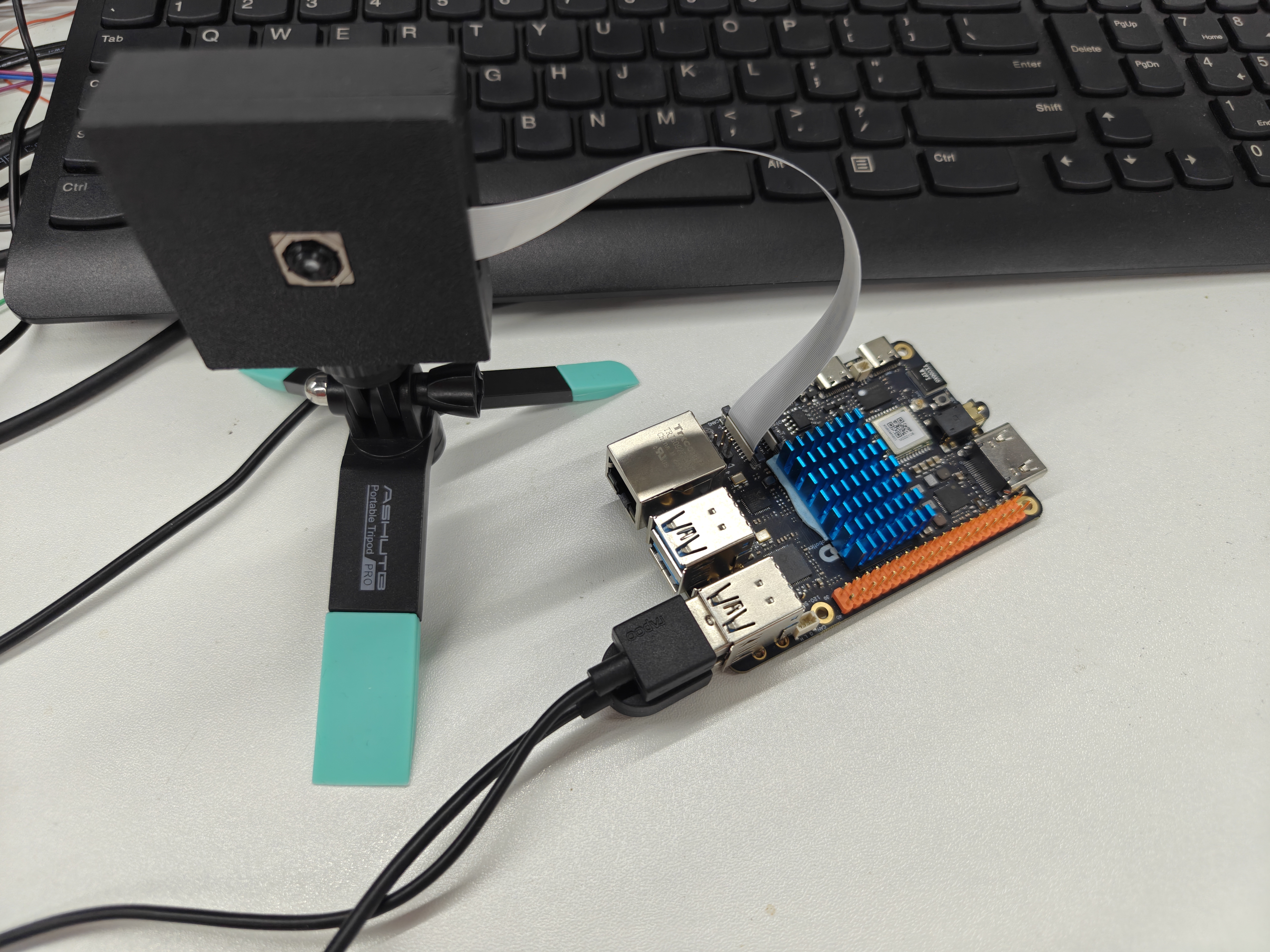
EVS camera connection diagram

Step 3: connect the display

  1. Use an HDMI cable to connect the RDK X5 and the display

Step 4: connect power

  1. Connect the power adapter
  2. Watch the board's indicator LEDs (they should start blinking)

2 Environment configuration

Reference docs

RDK official guide: https://developer.d-robotics.cc/rdk_doc/RDK

2.1 System login

2.1.1 HDMI desktop

Plug in power and HDMI, wait for the system to initialize, and the desktop will appear once initialization completes.
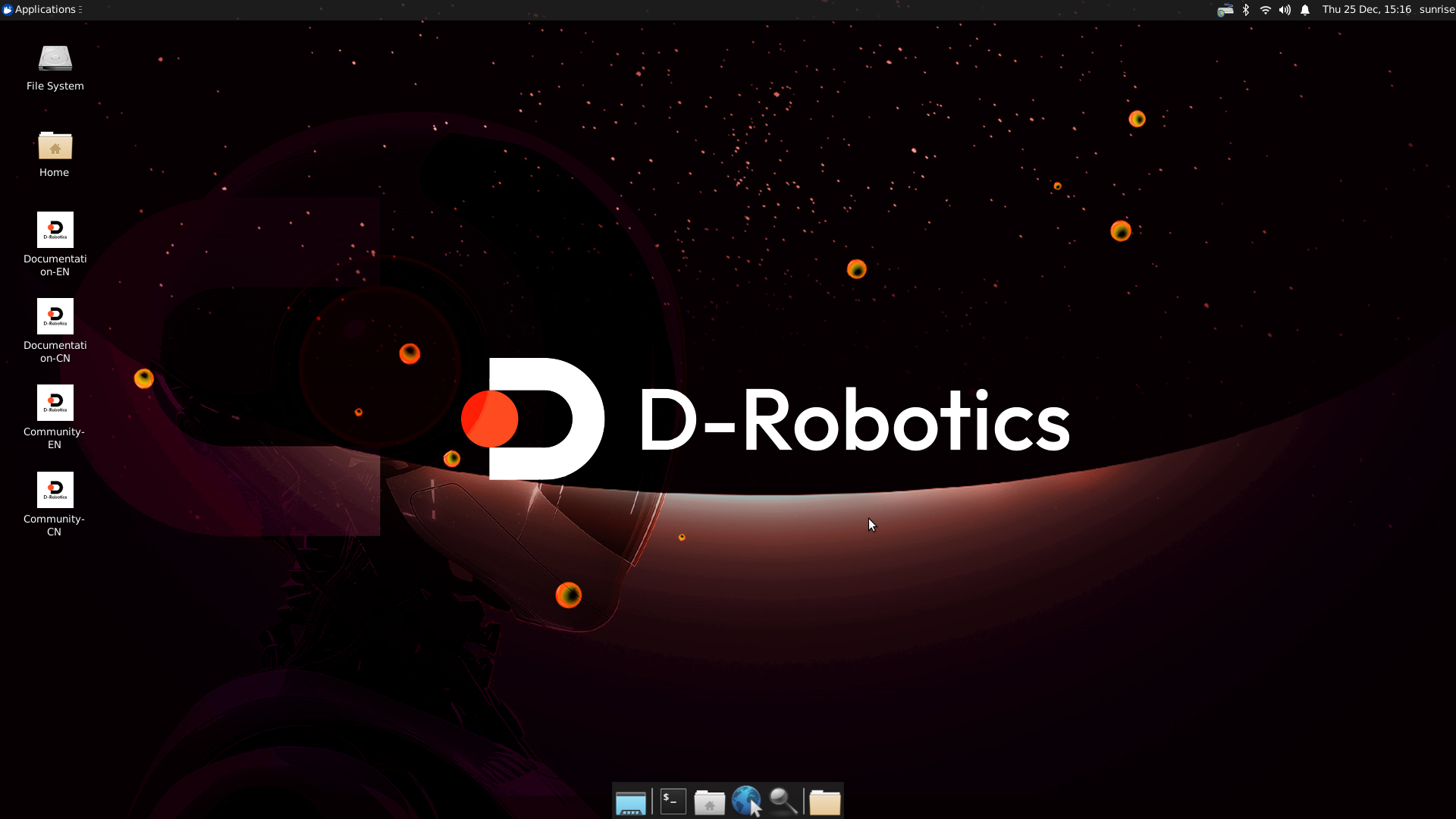
RDK desktop system

2.1.2 Serial login

To choose serial login, make sure the CH340 serial driver is installed. Plug in the serial adapter and a port will appear in Device Manager.

Device Manager - ports

Open MobaXterm, click Session, then select Serial; the X5 serial baud rate is 115200.
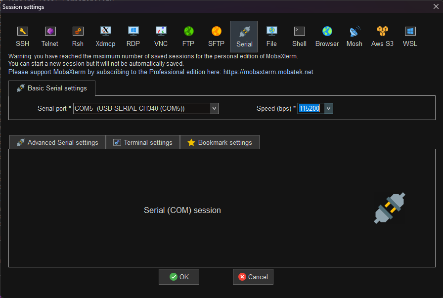
MobaXterm serial connection

Then plug in power to power on; logs will print in the MobaXterm serial terminal, and finally a system login appears. User: sunrise Password: sunrise User: root Password: root (administrator privileges)

03

2.2 MobaXterm SSH connection

If connected over WiFi, you can directly use the ifconfig command to get the current device IP.

If connected over Ethernet, enter the following command:

sudo vi /etc/NetworkManager/system-connections/netplan-eth0.nmconnection

Here we use the serial terminal as an example; you need to modify the IP address and gateway in this file to match the IP subnet of the Ethernet you are connected to.
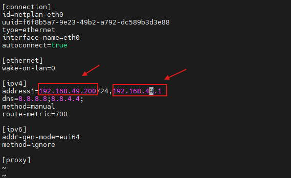
04

Then open MobaXterm, click SSH, and fill in the IP address and user (using root directly is recommended here).
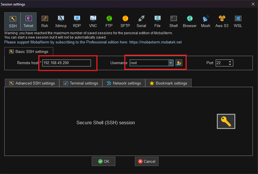
05

After clicking OK, enter the password to enter the terminal.
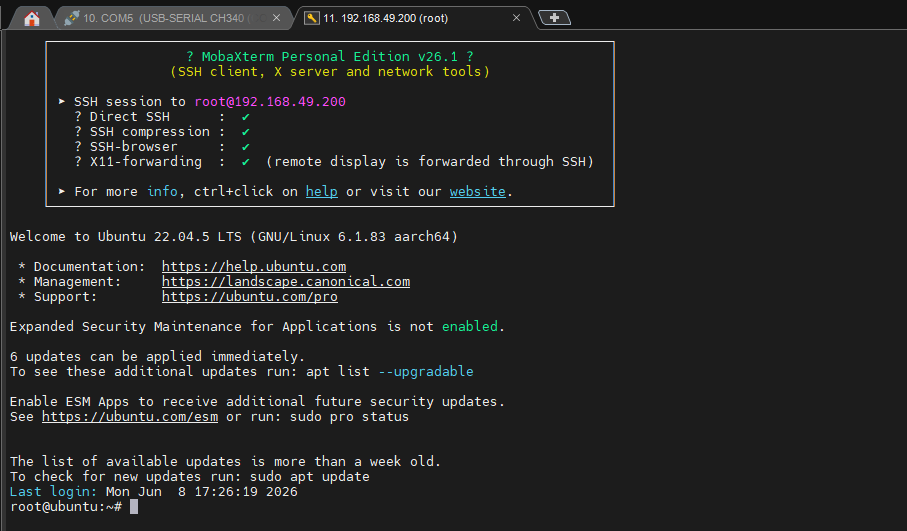
06

II. Sample program usage guide

The commands below are all run as the root user; under the sunrise user, prefix them with sudo.

1 Sample program directory layout

├── sample_aps              # APS 显示模式
│   └── get_aps_raw_display
│       ├── aps_display.cpp
│       └── Makefile
├── sample_evs_release      # EVS 案例包
│   ├── evs_env
│   │   ├── include
│   │   └── lib
│   ├── evs_mode
│   │   ├── 01_evs_live_player
│   │   ├── 02_evt2_to_csv
│   │   ├── 03_evs_recode_player
│   │   └── 04_raw8_to_evt2
│   └── Makefile
└── sample_hvs              # HVS 显示模式
    └── dual_vc_vin_src
        ├── dual_vc_vin.c
        ├── include
        ├── lib
        ├── Makefile
        └── src

2 sample_aps usage guide

2.1 APS real-time preview (get_aps_raw_display)

cd /app/multimedia_samples/sample_apx003cc/sample_aps/get_aps_raw_display
make

After running the above, a window showing the APS-mode image will appear on the Ubuntu desktop.

Note: this is currently only a demo; the ISP effect file has not yet been added. ISP effect files will be added later to enable RGB image display.

3 sample_evs_release usage guide

3.1 Real-time preview and recording (evs_live_player)

3.1.1 Function description

evs_live_player is the most basic sample program, providing two core functions:

  1. Real-time preview: displays the event-camera picture on the screen
  2. Data recording: saves the event data as a RAW8-format file

3.1.2 Preparation

Make sure:

  • ✓ The EVS module is correctly connected
  • ✓ A display is connected (for preview)

3.1.3 Usage

First enter the project directory, grant the program execute permission, and then list the available sensors:

cd /app/multimedia_samples/sample_apx003cc/sample_evs_release/evs_mode/01_evs_live_player
sudo ./evs_live_player.RAW8 -s 49

Note that only the apx003c-4096x256-240fps-4line configuration file is currently adapted; here we select index 49 to run.

After running:

  1. The program starts and opens the camera
  2. A preview window pops up showing the real-time picture
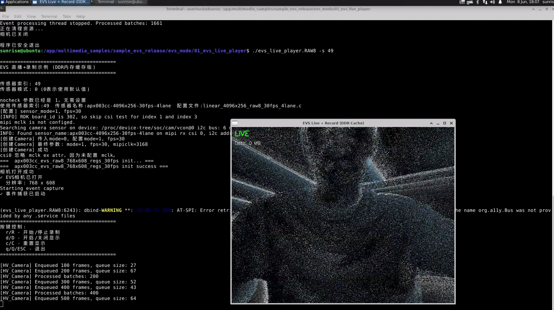
Real-time preview window

If you need to record, toggle recording on/off with the r shortcut; data is written to memory, and after recording ends it is written to the SD card (system card).
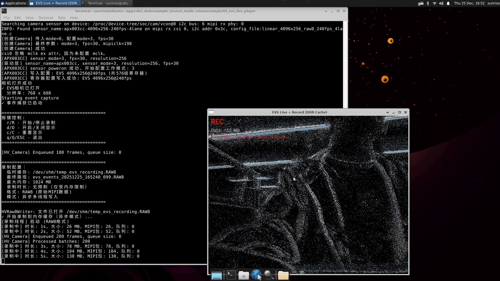
Recording process

After recording ends, the file is auto-named and saved to the current directory.

Warning

The module has an integrated encryption chip; this program only works with shimeta EVS modules.

3.1.4 FAQ

Here is an explanation of why data is first written to memory:

Because the RDK X5 has no integrated EMMC storage and only 4/8 GB of optional DDR4 memory, all system files are stored on the SD card. Most SD cards are not fast at non-sequential file read/write, and SD-card quality varies widely. A key feature of event cameras is high frame rate — although the data volume is not large, the frame rate is; the author understands that the frame rate of domestic event-camera sensors has reached as high as 64K!

Let's test the read/write speed of the SD card in use and the board's built-in DDR. The author's SD-card test results are below.

SD-card write test (12 MB/s):

dd if=/dev/zero of=/tmp/test_write bs=1M count=256 conv=fdatasync

SD-card read test (24 MB/s):

fio --name=read_test --ioengine=sync --rw=read --bs=1M --size=256M --numjobs=1 --filename=/tmp/test_write
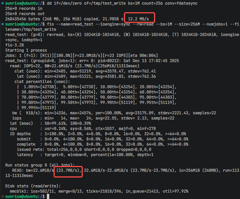
SD card read/write speed test

Memory read/write speed test (write 765 MB/s; read 1.7 GB/s):

Write test:

dd if=/dev/zero of=/dev/shm/memtest bs=1M count=1024 conv=fdatasync

Read test:

dd if=/dev/shm/memtest of=/dev/null bs=1M count=1024

Memory read/write speed test

Measured, the two differ in speed by nearly 100×! With recording on at a high frame rate, the SD-card read/write speed is clearly strained; buffering data in memory is a forced choice.


3.2 RAW8 to EVT2 (raw8_to_evt2)

Why convert?

Although the RDK X5 is advertised at 10 TOPS, that compute is concentrated on the BPU, while decoding mainly uses CPU resources. In testing, decoding the raw MIPI packets and displaying in real time is more than the CPU can handle — above 120 FPS the picture stutters noticeably. For real-time display, we only decode and display the first complete frame of each MIPI packet. When recording, the remaining raw data is saved directly to memory for later decoding. So why convert the raw data packets to EVT2 instead of analyzing them directly? Because EVT2 is the standard format of the Metavision SDK and is compatible with our Windows host software and the full Ubuntu algorithm library — so we provide the intermediate step of converting the saved raw data to EVT2.

Usage:

cd /app/multimedia_samples/sample_apx003cc/sample_evs_release/evs_mode/04_raw8_to_evt2

# 转换后的文件直接生成在当前目录
./raw8_to_evt2 /userdata/hand_wave.RAW8

# 指定转换后的文件到指定目录
./raw8_to_evt2 /userdata/hand_wave.RAW8 /userdata/output.raw

Conversion process:
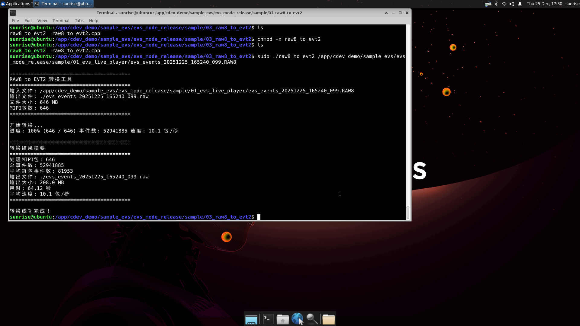
RAW8 to EVT2 conversion process

3.3 EVT2 to CSV (evt2_to_csv)

Why convert to CSV?

CSV is a universal table format, convenient for:

  • Viewing and analyzing in Excel
  • Data processing with Python/MATLAB
  • Plotting with visualization tools

CSV file format:

x,y,polarity,timestamp
352,240,1,1234567890
120,180,0,1234567920
425,305,1,1234568100
...
ColumnMeaningValue range
xabscissa0-767
yordinate0-607
polaritypolarity0 (darken) or 1 (brighten)
timestamptimestampmicroseconds

Usage:

cd /app/multimedia_samples/sample_apx003cc/sample_evs_release/evs_mode/02_evt2_to_csv

# 转换后的文件直接生成在当前目录
./evt2_to_csv /userdata/hand_wave.raw

# 指定转换后的文件到指定目录
./evt2_to_csv /userdata/hand_wave.raw /userdata/events.csv
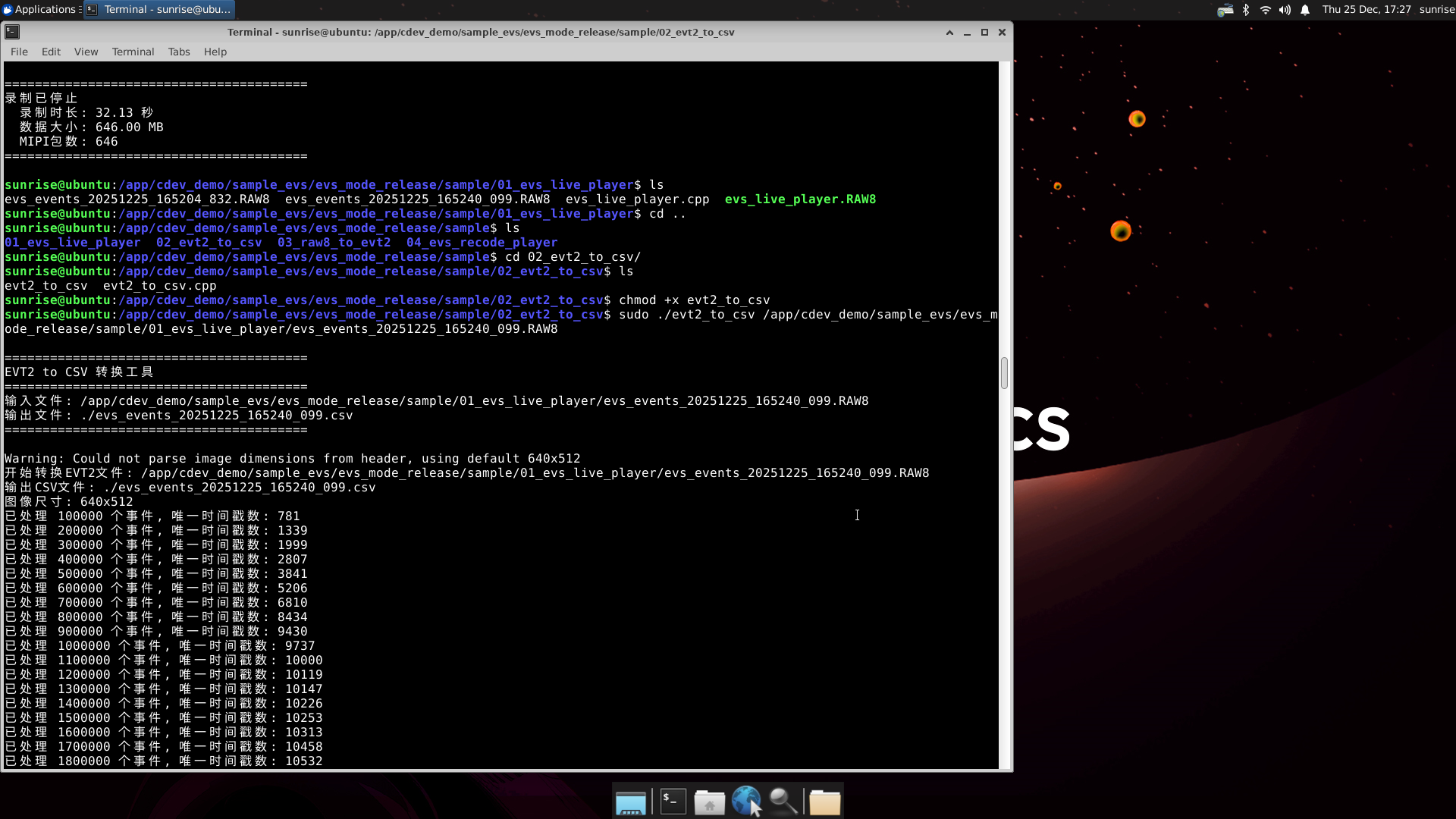
EVT2 to CSV conversion process

The converted text file can be opened directly for viewing.
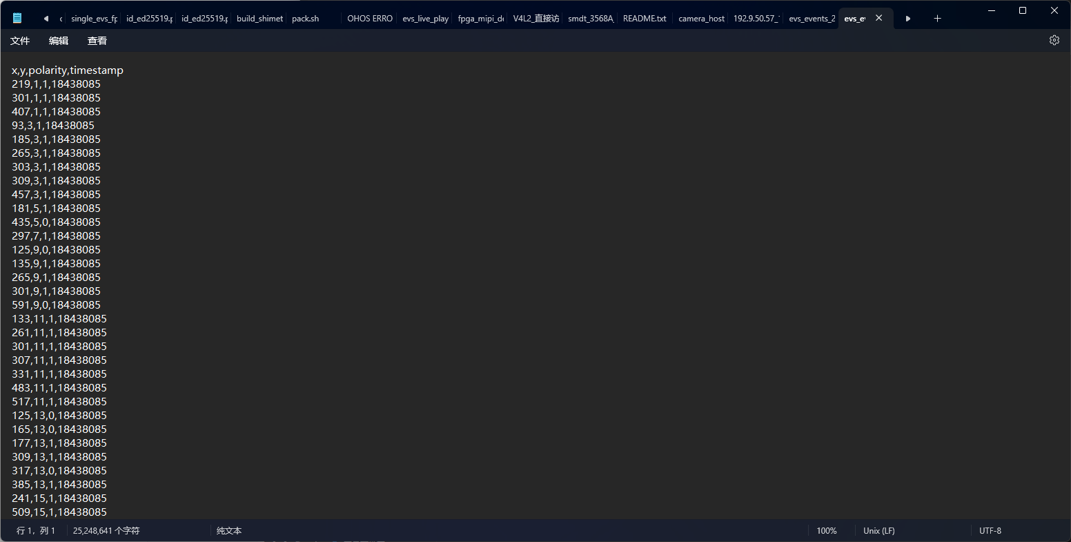
CSV file content

Note: do not casually open the converted file of a long recording — a pure txt file of several hundred MB will most likely freeze an underpowered computer.


3.4 Recording playback (evs_recode_player)

3.4.1 Function description

evs_recode_player is used to play back recorded event data and supports variable-speed playback (x1, x1/2, x1/8).

3.4.2 Usage

cd /app/multimedia_samples/sample_apx003cc/sample_evs_release/evs_mode/03_evs_recode_player

# 播放 EVT2 格式文件
./evs_recode_player /userdata/hand_wave.raw

3.4.3 Usage notes
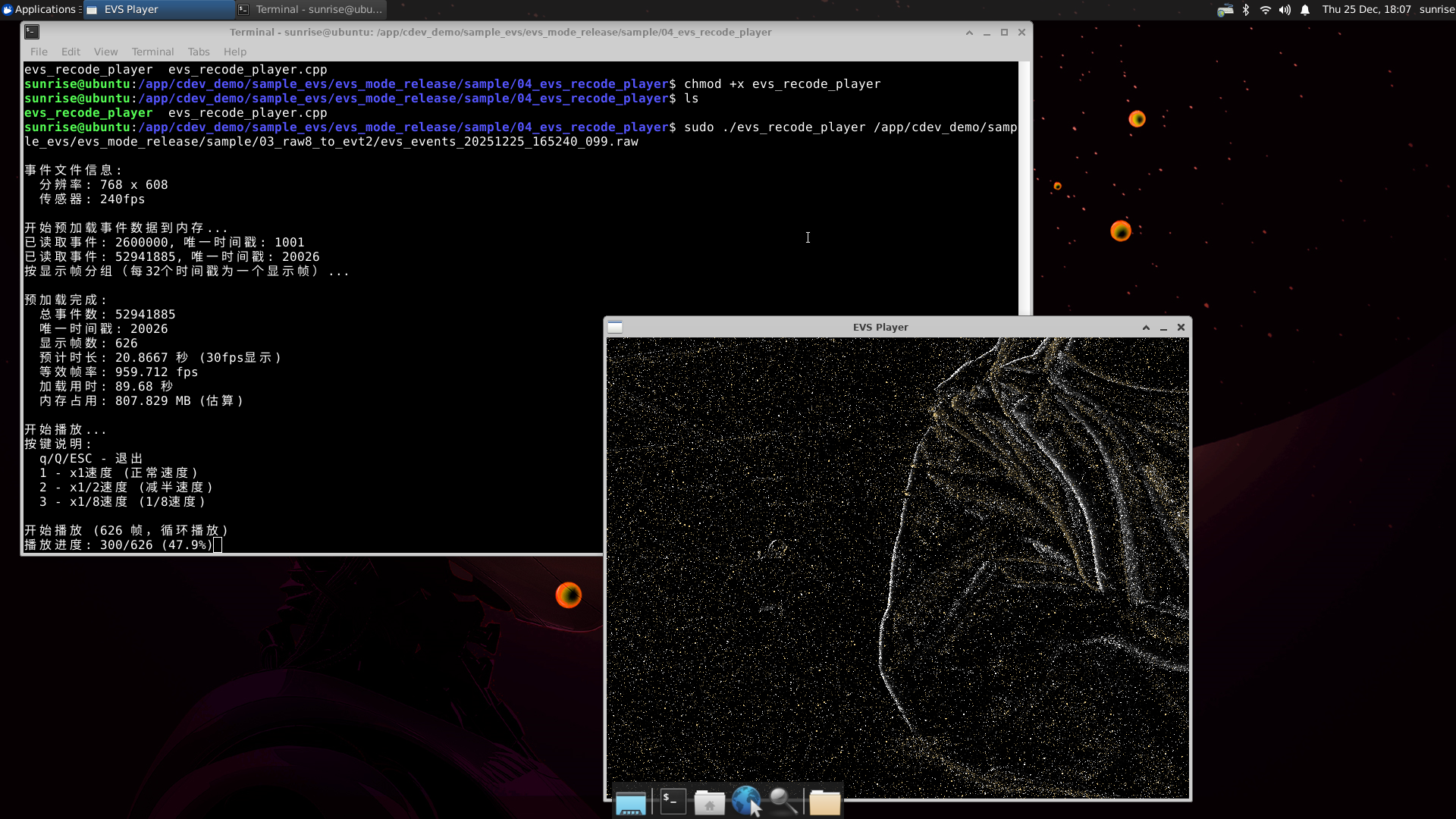
Playback window

The picture plays in a loop; press shortcut 1 for normal speed, 2 for 1/2 speed, 3 for 1/8 speed.

4 sample_hvs usage guide

4.1 HVS real-time display (dual_vc_vin_src)

Run the command below and a window showing the HVS-mode image (left EVS image + right APS image) will appear on the Ubuntu desktop.

cd /app/multimedia_samples/sample_apx003cc/sample_hvs/dual_vc_vin_src
./dual_vc_vin_src
make

Default parameters: -a 50 -b 51
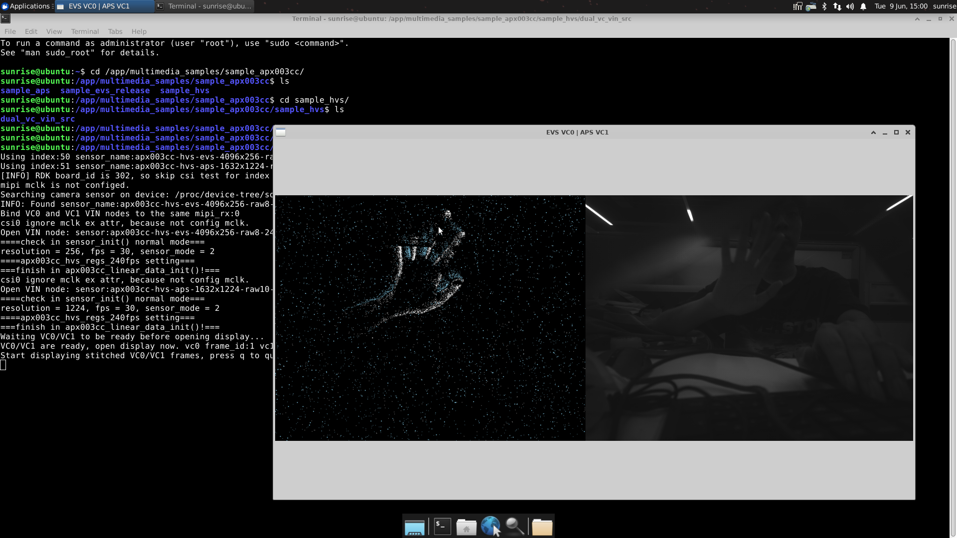
HVS real-time display

Note: this is currently only a demo; the ISP effect file has not yet been added. ISP effect files will be added later to enable RGB image display.

Edit this page on GitHub
Next
Raspberry Pi Carrier Board Adaptation